Cadence · Structural & Dynamic FEA Solver

Nastran: Structural, Dynamic, Thermal & Fatigue Analysis Capabilities

Nastran is a multidisciplinary finite element solver used to predict how a structure will deform, stress, vibrate, heat up, or fail before it's built. This page works through what the solver actually does — its core solution types, the workflow that connects them, and the industries that rely on each one — as a technical reference rather than a product pitch.

Solver ClassMultidisciplinary FEA solver
DeveloperHexagon / MSC Software (Cadence portfolio)
Core Solution TypesStatic, modal, dynamic, thermal, buckling, nonlinear
Model ScaleSingle bracket to full vehicle / airframe assembly
HistoryStructural solver standard since the 1970s
Overview

What Nastran actually is

Nastran — originally developed for NASA as the NASA STRuctural ANalysis solver — is a finite element solver, not a modeling or drawing tool. It takes a meshed, loaded, and constrained structural model and computes how that structure will displace, stress, vibrate, heat up, or fail under defined conditions. Distributed today as MSC Nastran under Hexagon's Manufacturing Intelligence division, it has been the reference structural solver behind commercial aircraft, automotive platforms, and industrial machinery for more than five decades, and remains one of the most widely used FEA codes for both automotive and aerospace vehicle design analysis.

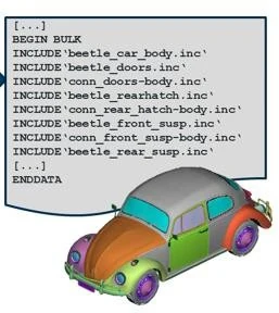
A Nastran model is assembled from text-based "bulk data" input files: geometry idealized into elements and nodes, material and property definitions, boundary conditions, and a solution sequence (SOL) that tells the solver which type of analysis to run. Because the format is modular — a model can reference separate INCLUDE files for each major sub-assembly — large programs can split a vehicle- or airframe-level model across teams and reassemble it without numbering conflicts, which is how automotive and aerospace programs commonly share one master structural model across NVH, durability, and nonlinear analysis groups.

Nastran operates a level deeper than the simplified simulation tools built into most CAD packages. It runs the full range of solution sequences — from linear statics through highly nonlinear, coupled, and dynamic analysis — on models scaled from a single bracket to a complete vehicle or airframe assembly, which is why it typically sits alongside, rather than instead of, a design team's everyday CAD environment.

Nastran bulk data input deck showing modular INCLUDE statements referencing separate sub-assembly files
A Nastran bulk-data input deck: large assemblies are built from modular INCLUDE files referencing individual sub-components, avoiding ID conflicts as models are exchanged between teams.
Analysis Capabilities

Twelve core solution types, explained

Each capability below is a distinct solution sequence or analysis technique inside Nastran. For each one: what it solves, why engineers reach for it, the industries that depend on it most, the results it produces, and the design decisions those results are actually used to make.

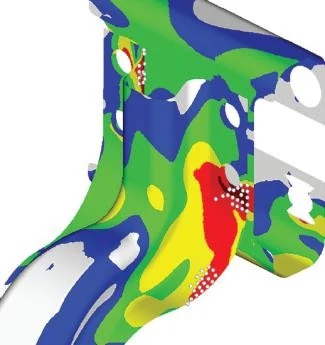
Static stress contour on a bracket assembly with the peak-stress region highlighted
Static stress contour on a bracket assembly, with the peak-stress region isolated — the detail engineers check first when sizing local reinforcement.
01

Linear Static Analysis

Linear static analysis (SOL 101) solves for displacement, stress, and strain under steady, non-time-varying loads, assuming the material stays within its elastic range and deflections stay small enough that stiffness doesn't change as the structure deforms. It's the fastest, most direct way to check whether a part or assembly can carry its design loads without yielding, and it's the baseline every deeper study is compared against.

Typical Industries
Industrial machinery, automotive structures, aerospace brackets and fittings, general mechanical design.
Expected Outputs
Displacement fields, von Mises and principal stress contours, reaction forces, margin-of-safety ratios.
Design Decisions Enabled
Sizing wall thickness, rib placement, fastener count, and material selection before tooling is committed.
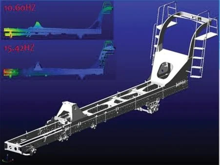
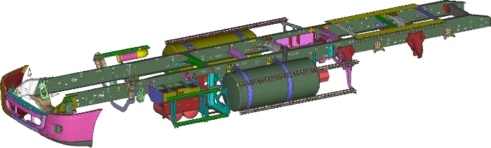
Assembled vehicle frame structural dynamics model used for frequency response analysis
A multi-part structural dynamics model of a vehicle frame assembly — the class of model used to evaluate frequency response across an operating speed range.
03

Frequency Response

Frequency response analysis (direct or modal, SOL 108/111) calculates how a structure's displacement, velocity, acceleration, or stress responds to loads that vary sinusoidally across a range of frequencies. It goes beyond modal analysis's "where are the resonances" to answer "how much will it actually move or stress at each frequency," accounting for damping and forcing amplitude rather than just natural frequency.

Typical Industries
Automotive NVH engineering, rotating equipment, electronics in vibrating environments, structural dynamics of machinery.
Expected Outputs
Frequency response functions (FRFs) — amplitude and phase of response versus excitation frequency at defined points.
Design Decisions Enabled
Confirming a component stays within vibration or noise limits across its full operating range, not just one worst-case point.
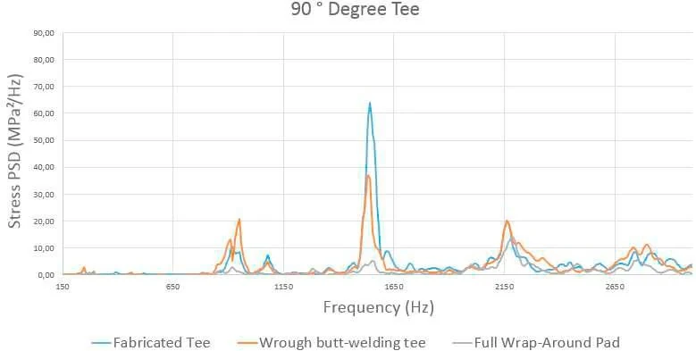
Stress power spectral density versus frequency chart comparing three joint design alternatives
Stress power spectral density (PSD) versus frequency for three alternative joint designs — the direct output of a random vibration analysis, compared here to select the most durable configuration.
04

Random Vibration

Random vibration analysis (SOL 111 with random response) uses power spectral density (PSD) inputs to predict the statistical stress and displacement response of a structure to broadband, non-deterministic excitation such as road roughness or transport vibration. Real vibration environments rarely look like a single clean sine wave, so this approach predicts RMS response and expected peak levels statistically rather than at one frequency at a time.

Typical Industries
Automotive and aerospace equipment in vibrating environments, electronics and avionics qualification, defense and transport equipment.
Expected Outputs
RMS stress and displacement, PSD response curves, expected peak values at a given probability level (1-sigma, 3-sigma).
Design Decisions Enabled
Verifying a design meets a qualification-test PSD profile before physical shaker testing, cutting the risk of late test failures.
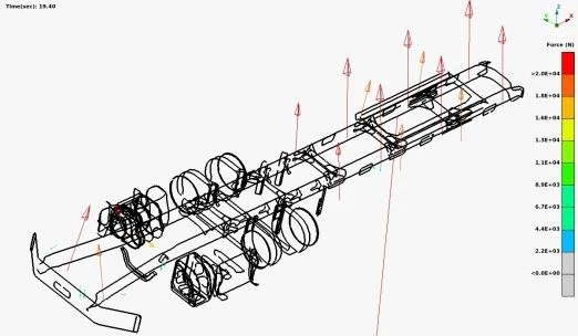
Wireframe structural model with applied load cases marked, used to evaluate stability against buckling
A wireframe structural model with applied load cases marked — the load-path information used to evaluate a frame's stability margin against buckling.
05

Buckling

Buckling analysis determines the load level at which a structure becomes unstable and its deformation pattern shifts suddenly and disproportionately. Linear buckling (SOL 105) estimates critical buckling load factors and mode shapes; nonlinear buckling traces the actual post-buckling load-deflection path. Thin-walled and slender structures can fail this way at loads well below their material strength limit — a failure mode a static stress check alone would miss entirely.

Typical Industries
Aerospace panels and stiffened structures, industrial equipment frames, pressure vessels, load-bearing brackets and columns.
Expected Outputs
Critical buckling load factors (eigenvalues) and buckled mode shapes; for nonlinear buckling, the full load-displacement curve.
Design Decisions Enabled
Setting minimum wall thickness, rib spacing, or stiffener layout so the buckling margin clears the operating load safely.
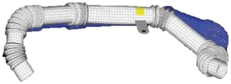
Finite element mesh of a routed pipe assembly used for thermal expansion analysis
A finite element mesh of a routed pipe assembly, representative of the thermal expansion and piping studies thermal analysis supports.
06

Thermal Analysis

Thermal analysis solves steady-state or transient heat transfer through conduction, convection, and radiation to predict the temperature distribution across a structure. Temperature gradients drive thermal expansion and change temperature-dependent material properties, so mapping the temperature field is the prerequisite step for any thermal-structural study that follows.

Typical Industries
Power electronics enclosures, automotive exhaust and powertrain components, industrial equipment in hot environments, piping systems.
Expected Outputs
Steady-state or time-history temperature fields, heat flux distributions, temperature gradients across critical interfaces.
Design Decisions Enabled
Sizing heat sinks, cooling paths, or insulation, and finding hot spots before they become thermal-stress or material problems.
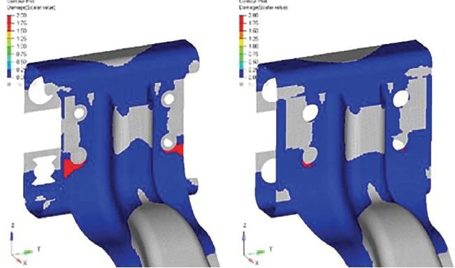
Comparative structural response of a mounting bracket evaluated across two operating conditions
Comparative structural response of a mounting bracket evaluated across two operating conditions — the type of before/after comparison used in coupled thermal-mechanical studies.
07

Thermal-Structural Coupling

Thermal-structural coupling feeds a temperature field from a thermal analysis into a structural solve, computing the stress and deformation caused by thermal expansion and temperature-dependent material properties. Components that operate across a wide temperature range — engine parts, transformers, piping, electronic assemblies — often see their largest stresses from thermal expansion mismatch rather than mechanical load alone, which a mechanical-only static analysis would miss.

Typical Industries
Automotive powertrain and exhaust systems, energy and transformer equipment, electronics packaging, piping and pressure equipment.
Expected Outputs
Thermally induced stress and displacement fields, and a comparison of stress state across two or more operating temperatures.
Design Decisions Enabled
Choosing materials and joint designs — expansion joints, compliant mounts, clearances — that accommodate thermal growth safely.
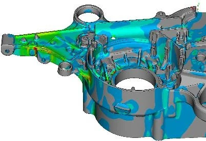
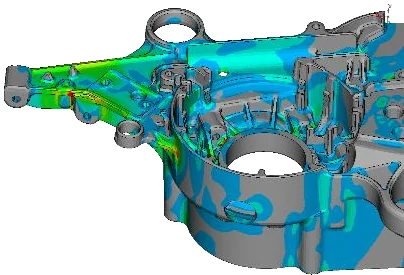
Stress contour on a differential housing showing a complex, contact-rich load path
Stress contour on a differential housing, showing the complex, contact-rich load path nonlinear structural analysis is built to capture.
08

Nonlinear Structural Analysis

Nonlinear structural analysis (SOL 400/401) solves problems where load and response aren't proportional — because of large deformation, changing contact, or nonlinear material behavior — using incremental, iterative solution methods rather than a single linear solve. Many real assembly and overload scenarios, from press-fits to sheet forming, simply cannot be represented accurately by a linear solution.

Typical Industries
Automotive body and chassis assemblies, off-highway and industrial equipment, consumer product housings, contact-heavy assemblies.
Expected Outputs
A full nonlinear load-response history, geometry- and material-corrected stress and strain fields, convergence diagnostics.
Design Decisions Enabled
Validating that an assembly sequence, snap-fit, or overload event behaves as intended, not just as small-deflection theory predicts.
Housing assembly showing bolted and bearing interfaces modeled with contact
The bolted and bearing interfaces on a housing assembly — the surfaces where contact modeling determines the real load path through a structure.
09

Contact

Contact modeling represents the interaction between separate bodies or surfaces that can touch, separate, or slide against each other, transferring load only where and when actual contact occurs — rather than assuming parts are permanently bonded. Bolted joints, bearing seats, bushings, and press-fit interfaces all depend on this physical reality; ignoring it overstates stiffness and can mask real stress concentrations at contact edges.

Typical Industries
Automotive suspension and driveline assemblies, industrial machinery with bolted or bearing interfaces, general mechanical assemblies.
Expected Outputs
Contact pressure distributions, gap or penetration status, transferred contact forces, stress concentrations at contact boundaries.
Design Decisions Enabled
Confirming bolt patterns, preload, and bearing clearances actually deliver the intended load path through an assembly.
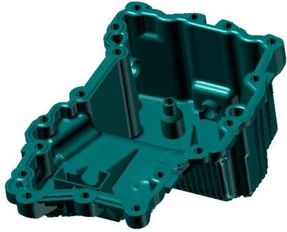
Stress contour on a cast oil pan housing, a thin-walled part suited to large-deflection analysis
Stress contour on a cast oil-pan housing — a thin-walled, large-surface part where geometry-updated, large-deflection analysis improves accuracy over small-deflection assumptions.
10

Large Deformation

Large deformation analysis accounts for geometric nonlinearity — cases where a structure's deflection is large enough that its stiffness changes measurably as it deforms — updating geometry and the stiffness matrix through the solution instead of assuming small-displacement theory holds throughout. Thin, flexible, or slender components can deflect enough that a small-deflection linear solve produces meaningfully wrong stress and displacement predictions.

Typical Industries
Sheet metal and stamped components, cast and molded housings, flexible brackets and covers, thin-section structures generally.
Expected Outputs
Deformed shape and stress state that reflect the structure's actual, geometry-updated stiffness at each load increment.
Design Decisions Enabled
Verifying clearances and stress levels hold up under realistic large-deflection conditions, not the small-deflection approximation.
11

Material Nonlinearity

Material nonlinearity covers structures whose stress-strain behavior departs from simple linear elasticity — plasticity, hyperelasticity in rubber, viscoelasticity, or other nonlinear constitutive laws — so the solver captures yielding, permanent set, or large elastic stretch correctly. Metals loaded beyond yield, elastomer seals and mounts, and many polymer components don't behave elastically; treating them as linear elastic either overstates stress by missing post-yield redistribution, or misses permanent deformation entirely. For composite and plastic parts, Nastran's nonlinear solvers can take calibrated material models directly from Digimat rather than relying on simplified, constant-property assumptions.

Typical Industries
Metal forming and overload analysis, elastomer seals and mounts, polymer and composite components.
Expected Outputs
Plastic strain and permanent-set predictions, post-yield stress redistribution, hyperelastic strain energy and stretch ratios.
Design Decisions Enabled
Confirming a part yields locally without failing globally, or that a rubber mount's stiffness stays in spec across its compression range.
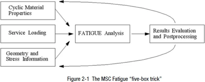
The MSC Fatigue five-box methodology diagram: material properties, service loading, and geometry combine into a fatigue analysis
The fatigue "five-box" methodology: material properties, service loading, and geometry/stress results combine into a fatigue analysis that outputs life predictions and design guidance.
12

Fatigue and Durability Preparation

Fatigue analysis combines stress or strain results — static, dynamic, or random-vibration — with material S-N (total life) or e-N (crack initiation) curves and duty-cycle loading to predict how many cycles, or how much service life, a structure can sustain before crack initiation. Most in-service structural failures are fatigue failures rather than single-overload failures, so predicting fatigue life digitally catches high-risk locations long before a physical durability test — or a field failure — does. Embedded fatigue workflows can also compute factor of safety and evaluate multiaxial loading directly from the structural results.

Typical Industries
Automotive chassis and suspension, industrial and off-highway equipment, piping and pressure systems, any cyclically loaded structure.
Expected Outputs
Fatigue life in cycles or time to crack initiation, damage accumulation maps highlighting the highest-risk locations, safety factor.
Design Decisions Enabled
Prioritizing which locations need local reinforcement, material change, or surface treatment to meet a target durability requirement.
Typical Workflow

How these capabilities connect in practice

A Nastran study rarely uses one capability in isolation — it moves through a defined sequence, and which solution types get used depends on the question being asked at each stage.

Idealize the geometry

CAD geometry is imported and idealized into a finite element mesh, with material and property definitions assigned to each part. Large assemblies are typically split into modular sub-files referenced by INCLUDE statements, so different teams can own different parts of the same master model.

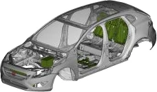
A vehicle body idealized into a finite element mesh
A vehicle body idealized into a finite element mesh — the geometry-to-model step every Nastran study starts from.

Define boundary conditions and loads

Constraints, connections between parts — welds, bolts, contact — and the load cases or dynamic excitation relevant to the study are applied. This is also where the analyst decides whether contact, large deformation, or material nonlinearity need to be represented explicitly.

Select the solution sequence

The SOL that matches the engineering question is chosen — linear statics, modal, frequency response, random vibration, buckling, thermal, or a coupled combination of several.

Solve

The solver runs, using parallel processing (SMP or DMP across multiple cores and nodes) or GPU acceleration for large models, with superelements available to reduce sub-assemblies to compact representations.

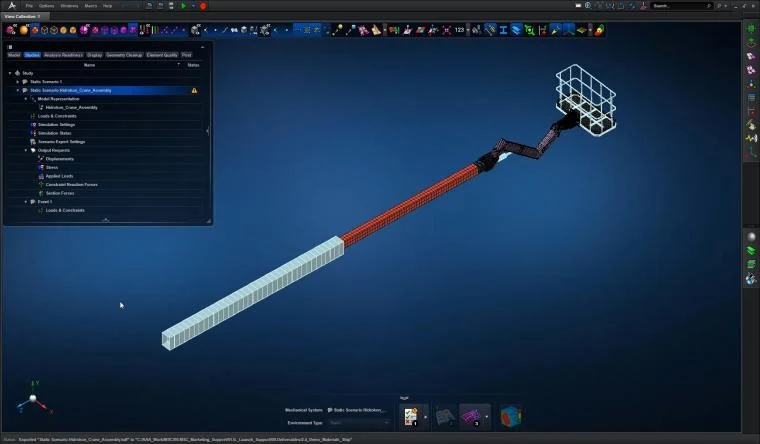
Pre-processing environment used to build and mesh a Nastran model
A pre-processing environment used to build and mesh a Nastran model before it's submitted to the solver.

Post-process, correlate, and iterate

Displacement, stress, frequency, or fatigue-life results are reviewed in Patran, MSC Apex, or a third-party post-processor, correlated against physical test data where it exists, and fed back into the next design iteration.

Applications by Industry

Where these capabilities are put to work

Automotive structural applications for Nastran
Automotive structures are among the most common Nastran applications, from body-in-white stiffness to chassis and suspension durability.

Automotive

Body-in-white stiffness and durability, chassis and suspension component sizing, powertrain mount design, and NVH work aimed at reducing interior noise and vibration.

Aerospace structural applications for Nastran
Aerospace structures — from airframe panels to engine mounts — rely on Nastran for certification-level structural and dynamic analysis.

Aerospace

Airframe structural certification, wing and fuselage panel buckling and stiffness checks, and engine mount and rotordynamics analysis.

Energy and oil and gas structural applications for Nastran
Piping and structural support systems in energy and oil & gas facilities, where vibration-induced fatigue is a leading cause of in-service failure.

Energy & Oil and Gas

Piping system vibration and acoustic-induced-vibration fatigue assessment, and structural support and skid design for rotating equipment.

Industrial and handheld equipment structural applications for Nastran
Industrial and handheld equipment housings, evaluated for structural and vibration performance under continuous duty cycles.

Industrial Machinery & Equipment

Frame and housing stiffness, vibration isolation, and structural qualification of handheld and stationary power equipment.

Interoperability

Where Nastran fits in a wider simulation stack

Nastran rarely runs in isolation. Model pre- and post-processing is typically handled in Patran or MSC Apex; nonlinear material behavior for plastics and composites is characterized in Digimat and passed to Nastran as calibrated material models; multibody dynamic loads from Adams can be imported directly as flexible-body representations for durability and fatigue studies; and vibro-acoustic problems are handed off to Actran, where Nastran's structural results become the vibration source.

Specialist nonlinear structural solver, often used alongside Nastran for the most severe contact and material nonlinearity cases.

Supplies calibrated composite and plastic material models directly into Nastran's nonlinear material nonlinearity workflow.

Provides fluid flow and convective boundary conditions that feed into Nastran's thermal and thermal-structural coupling studies.

Exports multibody dynamic loads and flexible-body representations that Nastran's structural models can consume directly.

Takes Nastran's structural vibration results as the excitation source for vibro-acoustic and noise radiation analysis.

FAQ

Frequently asked technical questions

What's the difference between modal analysis and frequency response analysis?

Modal analysis (SOL 103) finds a structure's natural frequencies and mode shapes independent of any applied load. Frequency response analysis (SOL 108/111) applies an oscillating load across a frequency range and computes the resulting displacement, velocity, or stress at each frequency — modal analysis tells you where the resonances are, frequency response tells you how much they matter under a defined excitation.

When is a nonlinear solution required instead of linear statics?

A nonlinear solve is needed when deflections are large enough to change the structure's stiffness, when contact between parts opens or closes during loading, or when the material is loaded beyond its linear-elastic range. If none of those apply, a linear static solution is faster and sufficiently accurate.

Can Nastran predict fatigue life directly, or does it require a separate tool?

Nastran's structural results — static, transient, or random-vibration stress — feed directly into fatigue post-processing, combining those results with S-N or e-N material curves and duty-cycle loading to compute cycles to failure and highlight high-risk locations.

How does Nastran handle very large assembly models?

Through modular bulk-data include files, superelements that reduce sub-assemblies to compact representations, and parallel solvers — SMP, DMP, and GPU acceleration — that distribute the computation across multiple cores, nodes, or GPUs.

Does Nastran integrate with the CAD environment our team already uses?

Yes. Nastran's bulk-data format imports geometry and mesh data from major CAD and pre-processing environments, and GTECH ASIA's implementation support covers fitting Nastran into an existing CAD-centric workflow rather than requiring a parallel toolchain.

What output formats does Nastran produce for post-processing?

Standard OP2, F06, and XDB result files, readable by Patran, MSC Apex, and most third-party post-processors, alongside plain-text F06 output for direct review of solver diagnostics and summary results.

GTECH ASIA supplies and supports Nastran licensing for engineering teams across Malaysia and Southeast Asia, with HRD Corp certified training available for teams building in-house analysis capability.