Cadence · Multibody Dynamics Solver

Adams: Multibody Dynamics Simulation Capabilities

Adams is a multibody dynamics solver that predicts how mechanisms, vehicles, and machinery actually move — the forces, motion, and loads produced by connected, moving parts — before a physical prototype exists. This page works through what the solver actually does, its core capabilities, the workflow that connects them, and the industries that rely on each one.

Solver ClassMultibody dynamics (MBD) solver — kinematics, dynamics, statics
DeveloperHexagon / MSC Software (Cadence portfolio)
Core Solution TypesRigid- & flexible-body dynamics, kinematics, linearization, co-simulation
Model ScaleA single joint or linkage to a full vehicle or driveline assembly
HistoryIndustry-standard MBD solver since the 1980s
Overview

What Adams actually is

Adams is not a structural solver and not a CAD tool — it's a multibody dynamics (MBD) solver that predicts the motion, velocity, acceleration, and interconnection forces of a system built from multiple rigid or flexible bodies connected by joints, springs, dampers, actuators, and contacts. Where a structural FEA solver like Nastran answers "how does this one part deform under a known load," Adams answers a different question first: "what are the loads, at every instant, as this assembly of moving parts actually operates?"

An Adams model is built from bodies, connections (revolute, translational, spherical, and other joint types), and force elements assembled into a mechanism or vehicle topology. The solver then integrates the system's equations of motion through time — or, for simpler questions, solves kinematics alone. The current Adams Modeler interface, built on the Apex platform, brings CAD-associative model building to this process: geometry features can be picked directly to place joints and forces, and flexible bodies can be generated from rigid CAD parts with a largely automated meshing step.

Adams sits upstream of, and often feeds, structural and durability analysis. Because it produces the actual time-varying loads a mechanism or vehicle experiences in operation — not an assumed static load case — those loads are frequently exported directly into Nastran or Marc as boundary conditions for stress, fatigue, and durability studies, closing the loop between "how does it move" and "will it survive."

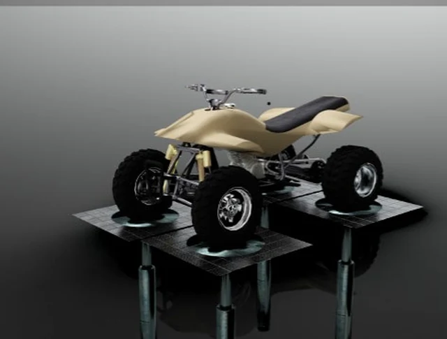
A multibody model of an ATV chassis and suspension assembly mounted on a four-post durability shaker rig
A full-vehicle multibody model prepared for durability and road-load simulation on a four-post shaker rig — a textbook Adams application.
Capabilities

Eight core capabilities, explained

Each capability below is a distinct function inside Adams. For each one: what it solves, why engineers reach for it, the industries that depend on it most, the results it produces, and the design decisions those results are actually used to make.

01

Rigid-Body Kinematics & Dynamics

Rigid-body analysis treats every part in a mechanism as non-deformable and solves for its position, velocity, acceleration, and the forces transmitted through each joint as the system moves. Kinematic analysis is used when the motion is fully prescribed by the mechanism's geometry and constraints — a four-bar linkage driven at a fixed input speed, for example. Dynamic analysis goes further, solving Newton-Euler equations of motion so that motion emerges from applied forces, masses, and inertias rather than being prescribed directly. This is almost always the first model built for a new mechanism, because it establishes the baseline motion envelope and joint loads that later, more detailed studies are compared against.

Typical Industries
General mechanism design, industrial machinery, robotics, consumer product mechanisms.
Expected Outputs
Position, velocity, and acceleration time histories; joint reaction forces and torques; range-of-motion envelopes.
Design Decisions Enabled
Confirming a mechanism reaches its required travel and speed without interference, and sizing joints and actuators to the loads they'll actually see.
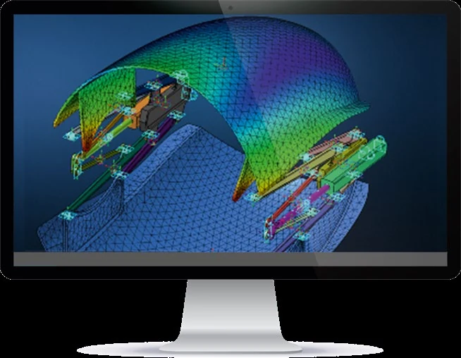
A flexible body finite-element mesh with a stress contour integrated into a multibody deployable mechanism
A flexible body — represented with its own FE mesh and deformation contour — integrated directly into a multibody mechanism.
02

Flexible-Body Multibody Dynamics

Real components deflect under load, and that deflection can change how a mechanism behaves — a long linkage arm may bend enough in operation to alter contact timing, or a panel may flex and vibrate as it's actuated. Flexible-body dynamics represents selected parts as finite-element-based flexible bodies within the multibody model instead of rigid links, so the solver captures both the rigid-body motion of the system and the elastic deformation of individual components simultaneously. Adams Modeler generates these flex bodies directly from rigid CAD parts through an automated meshing step, keeping them associative to the source geometry.

Typical Industries
Automotive body and closure mechanisms, aerospace deployable structures, industrial equipment with large or thin moving members.
Expected Outputs
Combined rigid-motion and elastic-deformation results; modal participation in the flexible body's response; deformed shapes during operation.
Design Decisions Enabled
Determining whether a part needs added stiffness to keep a mechanism's motion and timing within spec, before committing to a rigid-only assumption.
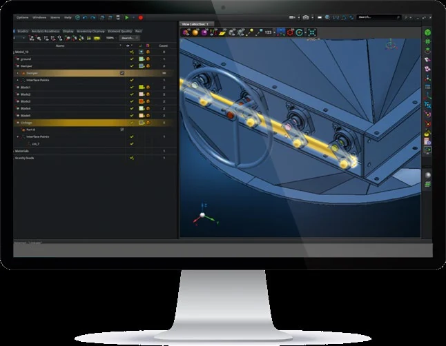
Adams Modeler interface showing a model tree of bodies and connectors alongside a 3D mechanical assembly
A model tree of bodies, joints, and force elements — the structure that defines how a mechanism's parts actually connect and interact.
03

Joint, Force & Contact Modeling

The behavior of any mechanism is defined as much by its connections as by its parts — revolute, translational, cylindrical, and spherical joints; springs, dampers, and bushings with linear or nonlinear force-deflection characteristics; and contact elements that transfer load only where and when two surfaces actually touch. Adams Modeler's CAD-associative workflow lets engineers pick geometric features directly to place these connections. Getting these definitions right is what separates a model that predicts real system behavior from one that only looks plausible.

Typical Industries
Automotive suspension and driveline, industrial machinery, robotics, off-highway equipment linkages.
Expected Outputs
Joint reaction forces and torques, contact pressure and force at defined interfaces, spring and damper force-deflection curves.
Design Decisions Enabled
Sizing bushings, dampers, and joint hardware to the actual transmitted loads, and confirming contact-dependent behavior across a full range of motion.
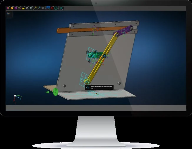
Adams Modeler screenshot mid-workflow, selecting entities to associate with a geometry part
Geometry-feature picking mid-workflow — associating a joint directly with the CAD part it belongs to, rather than a disconnected reference point.
04

CAD-Associative Model Building

Rather than treating geometry import as a one-time step, Adams Modeler maintains a generative relationship between CAD geometry and the multibody model built on top of it: model objects — joints, forces, flex bodies — stay associated with the geometric features that define them, so a geometry change regenerates the affected model objects instead of breaking the model outright. Engineers can edit geometry features directly without needing a round-trip back to the CAD group for every design iteration.

Typical Industries
Any CAD-driven mechanism design process — automotive, industrial machinery, consumer products, off-highway equipment.
Expected Outputs
A motion model that regenerates automatically from CAD updates, with joints, forces, and flex bodies remaining correctly positioned.
Design Decisions Enabled
Running design-iteration loops directly in the simulation environment, without waiting on a separate CAD update cycle for every geometry change.
05

Vehicle Dynamics & Full-Vehicle Modeling

Vehicle dynamics modeling assembles suspension, steering, powertrain, and tire subsystems into a full-vehicle multibody model to predict handling, ride, and stability characteristics — how the vehicle responds to steering input, road undulation, braking, and cornering loads. Suspension kinematics and compliance under load are solved together with vehicle-level maneuvers, using specialized tire models to represent the tire-road force interface realistically. Because these are multibody systems by nature, a full-vehicle dynamic model captures interaction effects between subsystems that isolated component checks cannot.

Typical Industries
Automotive OEM and supplier vehicle dynamics groups, off-highway and heavy equipment manufacturers.
Expected Outputs
Suspension kinematic and compliance curves, vehicle handling metrics, ride comfort measures, component load histories under defined maneuvers.
Design Decisions Enabled
Tuning suspension geometry, bushing rates, and steering linkage design to hit target handling and ride characteristics before physical prototypes exist.
06

Durability Load Extraction for Structural FEA

A structural fatigue or durability study is only as good as the loads fed into it, and for any moving assembly, those loads are a direct product of the system's kinematics and dynamics — not a simplified static assumption. Adams computes the time-varying forces at every joint and interface as a mechanism or vehicle operates through a representative duty cycle, and those load histories, together with flexible-body representations of individual components, can be exported directly into Nastran or Marc for stress and fatigue analysis.

Typical Industries
Automotive chassis and suspension durability, off-highway equipment structural analysis, industrial machinery structural qualification.
Expected Outputs
Time-history load channels at each joint and interface, flexible-body load cases formatted for structural FEA import.
Design Decisions Enabled
Basing structural sizing and fatigue-life targets on real dynamic operating loads rather than conservative or simplified static estimates.
07

Co-Simulation with Control Systems

Many mechanisms and vehicles today are not purely mechanical — their motion is shaped by an active control system, whether that's an anti-lock braking controller, an active suspension, or a robotic motion controller. Co-simulation couples the Adams multibody model with a controls environment such as Simulink, running both simultaneously so that the mechanical system's response feeds the controller's sensed inputs, and the controller's commanded outputs feed back as forces or motion into the mechanical model, at each solver time step. This is the only way to evaluate a mechatronic system's real closed-loop behavior.

Typical Industries
Automotive active safety and chassis control systems, robotics, aerospace actuation systems, industrial automation.
Expected Outputs
Coupled mechanical-and-control time-history results, closed-loop system response to defined control inputs and disturbances.
Design Decisions Enabled
Tuning control gains and mechanical hardware together, rather than assuming an idealized mechanical response when designing the controller.
08

Linearization & Vibration Modes of Mechanisms

A multibody mechanism's dynamic behavior is generally nonlinear — its effective stiffness and inertia change as it moves through its range of motion — but at any single configuration, the system's equations of motion can be linearized to extract natural frequencies and mode shapes, much as a structural modal analysis would for a fixed structure. This identifies vibration modes and resonance risk specific to a mechanism's operating position, which matters because a mechanism's dynamic characteristics at full extension can differ substantially from its characteristics at mid-travel or full retraction.

Typical Industries
Automotive suspension and driveline, aerospace deployable mechanisms, industrial equipment with cyclic or reciprocating motion.
Expected Outputs
Natural frequencies and mode shapes evaluated at a specified mechanism configuration, eigenvalue-based stability indicators.
Design Decisions Enabled
Identifying configurations where a mechanism's natural frequency risks coinciding with an operating excitation, before it shows up in testing.
Typical Workflow

How these capabilities connect in practice

An Adams study moves from geometry, through motion and load results, to a structural solver downstream.

Build or import the multibody model

CAD geometry is imported and organized into the bodies that will make up the mechanism, using Adams Modeler's associative, drag-and-drop workflow to align the CAD structure with the intended model topology.

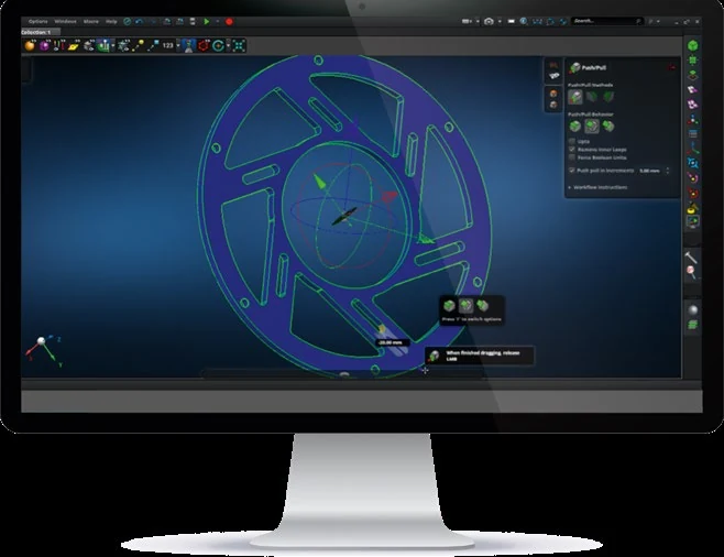
Direct geometry editing on a wheel/hub part in Adams Modeler using a push/pull tool
Direct geometry editing inside the multibody environment — pushing and pulling faces without a round-trip back to CAD.

Define joints, forces, and contacts

Revolute, translational, and other joint types are placed using geometry-feature picking; springs, dampers, bushings, and contact elements are added where the mechanism's real interfaces require them.

Choose rigid or flexible representation

Parts whose compliance affects the system's motion or load path are converted to flexible bodies through the automated flex-body generation step, while parts adequately represented as rigid are left as-is.

Run kinematic or dynamic simulation

A kinematic solve is used when motion is fully prescribed by the mechanism's constraints; a dynamic solve is used when motion needs to emerge from applied forces, masses, and inertias, including any co-simulated control system.

Extract loads or motion results

Joint forces, contact loads, displacement and acceleration time histories, and — where relevant — linearized natural frequencies are reviewed against the mechanism's performance requirements.

Export loads to a structural solver and iterate

Time-varying loads and flexible-body results are exported to Nastran or Marc for stress and durability analysis, results are correlated against physical test data where available, and the multibody model is updated for the next design iteration.

Applications by Industry

Where these capabilities are put to work

Automotive & Vehicle Dynamics

Full-vehicle handling and ride simulation, suspension kinematics and compliance tuning, steering linkage design, and driveline dynamics, alongside durability load extraction for chassis and suspension component fatigue studies.

Aerospace Mechanisms

Landing-gear deployment and retraction dynamics, control-surface actuation linkages, and other deployable mechanisms where motion, timing, and joint loads must be verified across the full range of operation.

Industrial Machinery

Linkage and cam mechanism design, robotic motion analysis, and machine dynamics studies where joint loads and cycle timing directly affect equipment reliability and throughput.

Off-Highway & Heavy Equipment

Boom, arm, and linkage dynamics for excavators, loaders, and similar equipment, plus suspension and driveline load extraction feeding into structural durability analysis for frames operating in high-load, high-cycle environments.

Interoperability

Where Adams fits in a wider simulation stack

Adams exports time-varying joint and interface loads, along with flexible-body representations of individual components, directly into Nastran and Marc for structural stress and fatigue analysis. Digimat-characterized material models can inform the structural properties assigned to flexible bodies representing composite or plastic components. Co-simulation couples Adams with controls environments such as Simulink so mechanical and control-system behavior are solved together.

Receives time-varying joint and interface loads, along with flexible-body representations, for structural stress and durability analysis.

Imports Adams flexible-body results as Modal Neutral Files, including nonlinear preload effects, for coupled nonlinear durability studies.

Supplies calibrated material properties for flexible bodies representing composite or plastic mechanism components.

Controls Environments

Simulink and similar tools co-simulate with Adams so mechanical motion and active control logic are solved together, not in isolation.

FAQ

Frequently asked technical questions

What's the difference between a kinematic and a dynamic simulation in Adams?

A kinematic simulation is used when a mechanism's motion is fully determined by its geometry and constraints, so no force balance is solved. A dynamic simulation solves the full equations of motion, letting position, velocity, and acceleration emerge from applied forces, masses, and inertias, and is required whenever the mechanism has unconstrained degrees of freedom or the forces themselves are the quantity of interest.

When does a part need to be modeled as flexible instead of rigid?

When the part's deflection under operating loads is large enough to meaningfully change the mechanism's motion, timing, or load path — long or thin linkage members, large panels, or components whose natural frequency falls within the mechanism's operating range are typical candidates. If a part's stiffness is high relative to the loads it sees, a rigid-body representation is faster to solve and sufficiently accurate.

How do loads from Adams get used in a fatigue or durability study?

Adams computes time-varying forces at every joint and contact interface as the mechanism or vehicle runs through a representative duty cycle. Those load time-histories, together with flexible-body data for the components involved, are exported to Nastran or Marc, where they're combined with material S-N or e-N curves to predict fatigue life — using real dynamic loading rather than an assumed static equivalent.

What is co-simulation, and when is it needed?

Co-simulation runs the Adams multibody model and a controls environment like Simulink together, exchanging data at each solver time step so the mechanical system's motion feeds the controller's inputs and the controller's outputs feed back as forces or motion into the mechanical model. It's needed whenever a mechanism's behavior is shaped by active control — braking systems, active suspensions, robotic actuation.

How does Adams Modeler differ from Adams View?

Both run on the same underlying Adams solver. Adams Modeler is a newer interface built on the Apex platform, aimed at simplifying core mechanism-modeling tasks through CAD-associative geometry picking, drag-and-drop assembly restructuring, and automated flexible-body generation. Adams View remains available for its established, more detailed modeling capabilities, and the two interfaces interoperate.

Can Adams evaluate vibration and resonance risk, or is that a structural-analysis-only question?

Adams can linearize a mechanism's equations of motion at a given operating configuration to extract natural frequencies and mode shapes specific to that position — useful because a mechanism's dynamic characteristics can change substantially across its range of travel. This complements, rather than replaces, a full structural modal analysis of individual components in a solver like Nastran.

GTECH ASIA supplies and supports Adams licensing for engineering teams across Malaysia and Southeast Asia, with HRD Corp certified training available for teams building in-house multibody dynamics capability.