Cadence · Multi-Scale Material Modeling Platform

Digimat: Multi-Scale Material Modeling for Composites & Reinforced Plastics

Digimat predicts how a plastic or composite material actually behaves — from its microstructure up — and turns that prediction into a calibrated material model a structural solver can use. This page works through what the platform actually does, its core capabilities, the workflow that connects them, and the industries that rely on each one.

Platform ClassMulti-scale material modeling / micromechanics engine
Developere-Xstream engineering — Hexagon (Cadence portfolio)
Core Solution TypesMicromechanics, process-coupled mapping, virtual testing & allowables
Model ScaleFiber/filler microstructure (microns) to a full structural part
HistoryIn continuous development since the early 2000s
Overview

What Digimat actually is

Digimat is not a structural solver — it's a materials engine. It predicts the nonlinear, often anisotropic, mechanical behavior of composite and other heterogeneous materials by modeling their microstructure directly: the properties of each phase (matrix, fiber, filler), the shape and aspect ratio of the reinforcement, and — critically — its local orientation and volume fraction as it actually exists inside a molded or laid-up part, rather than as a single averaged property. That microstructure model is homogenized mathematically into a macroscopic material response that a finite element solver can consume.

The practical output of Digimat is a material model: a set of constitutive equations and, where the microstructure varies from point to point across a part, spatially-varying material properties defined at each integration point of a finite element mesh. A metal part is reasonably represented by one isotropic property set, but a fiber-reinforced plastic part molded through a gate will have fiber orientation, and therefore stiffness and strength, that changes continuously across the geometry. Digimat is built specifically to capture and carry that variation through to the structural analysis.

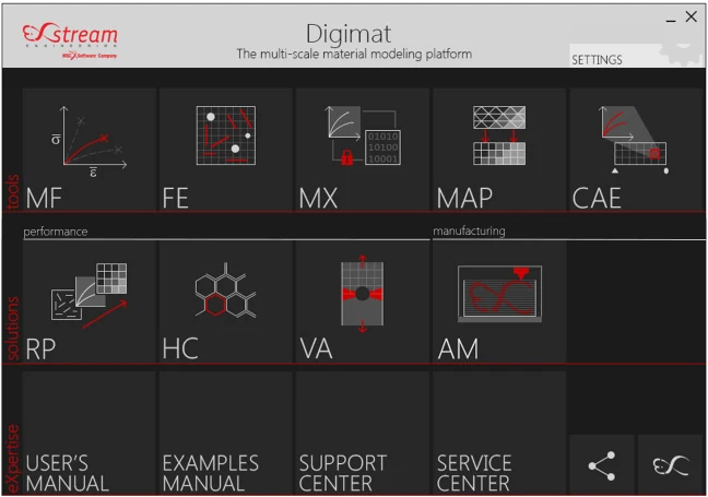
Digimat ships as a modular product family — Digimat-MF and Digimat-FE for micromechanical modeling, Digimat-MX for material data management and reverse engineering, Digimat-MAP for mapping data between dissimilar meshes, Digimat-CAE and Digimat-RP for coupling into structural solvers, plus specialist modules for sandwich panels (Digimat-HC) and virtual allowables (Digimat-VA). GTECH ASIA's own Digimat + Marc offering for transfer molding and semiconductor package reliability is one applied configuration of this platform.

Digimat software launcher showing its modular product suite: MF, FE, MX, MAP, CAE, RP, HC, VA, and AM
Digimat's modular product family — a materials engine built from purpose-specific tools rather than a single monolithic application.
Capabilities

Eight core capabilities, explained

Each capability below is a distinct function inside the Digimat platform. For each one: what it solves, why engineers reach for it, the industries that depend on it most, the results it produces, and the design decisions those results are actually used to make.

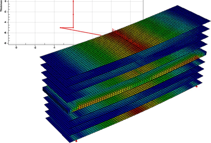
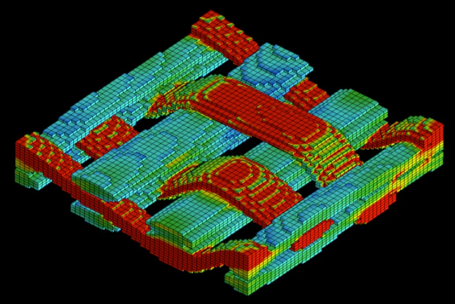
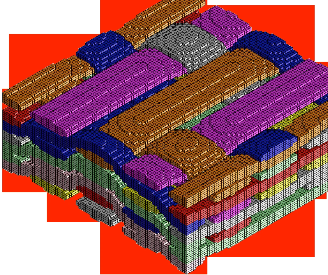
Voxelized multi-layer composite microstructure model
A voxelized representative volume element (RVE) of a layered composite — the microstructure-explicit model behind Digimat-FE homogenization.
01

Micromechanical Material Modeling

Digimat-MF (mean-field homogenization) and Digimat-FE (representative volume element homogenization) compute the macroscopic mechanical response of a composite from the properties of its individual phases — matrix, fiber, filler, coating, void — combined with a description of the microstructure: filler content, aspect ratio, orientation distribution, and layering. Digimat-MF solves this rapidly using schemes such as Mori-Tanaka; Digimat-FE builds and meshes an actual RVE and solves it directly, trading speed for a more direct, geometry-explicit view of the microstructure.

Typical Industries
Material suppliers developing new compound formulations, automotive and electronics Tier 1s, composite part designers.
Expected Outputs
Homogenized stiffness, strength, creep, fatigue, and thermal/electrical conductivity predictions; RVE stress and strain fields.
Design Decisions Enabled
Screening filler content, fiber type, or aspect ratio before running a physical material qualification program.
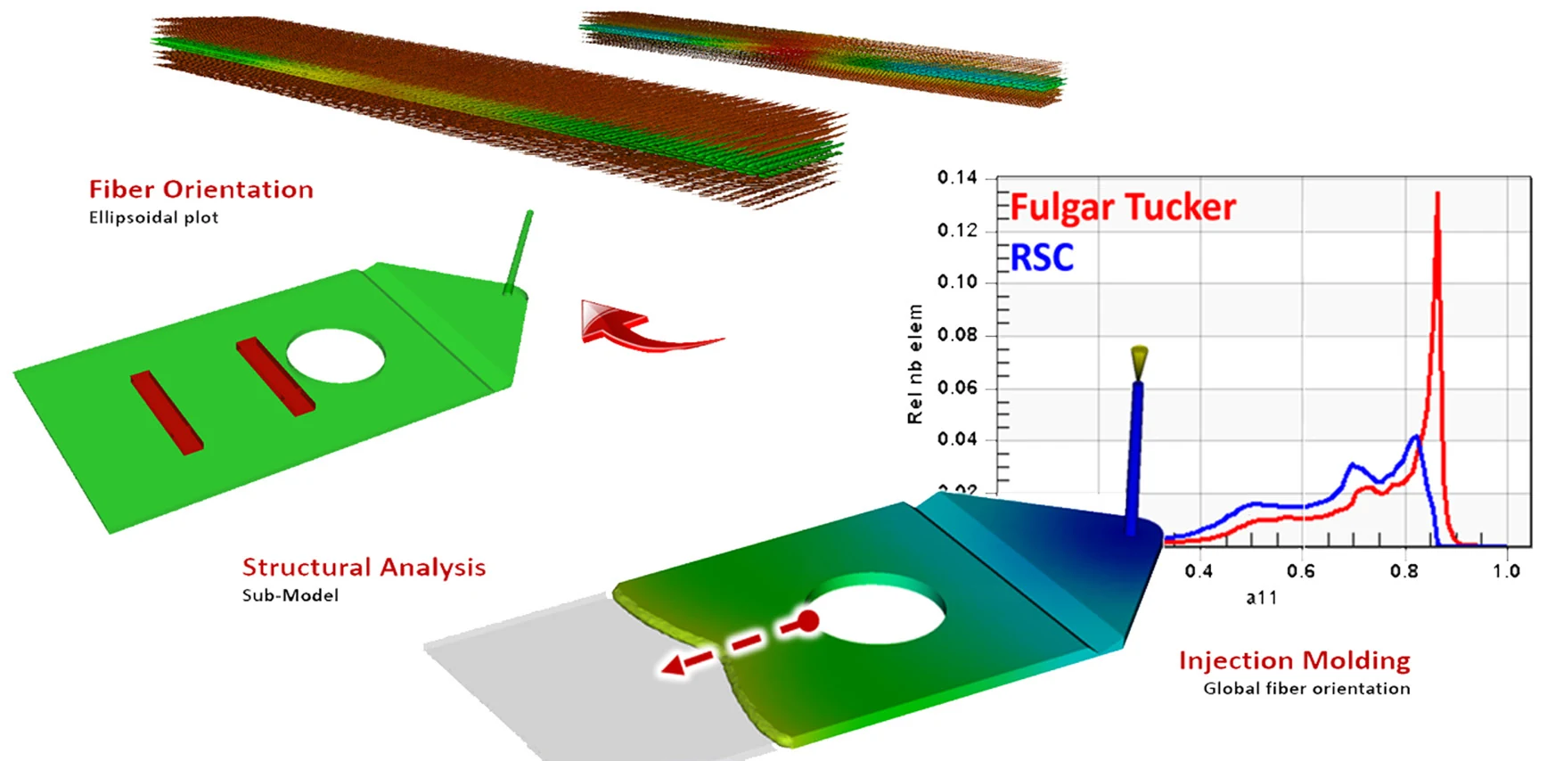
Fiber orientation ellipsoidal plot, structural sub-model, and injection molding global fiber orientation chart
Local fiber orientation read from an injection molding simulation and carried into a structural sub-model — comparing two orientation-prediction methods.
02

Fiber Orientation Prediction from Process Simulation

Digimat-RP reads local fiber orientation, volume fraction, and aspect ratio directly from an injection, injection-compression, or compression molding simulation and feeds that distribution into a micromechanical material model. Because manufacturing process conditions — gate location, flow front behavior, wall thickness — physically orient the fibers as the part fills, a part's real stiffness and strength distribution rarely matches the simple assumption of uniformly oriented reinforcement.

Typical Industries
Automotive structural and under-hood components, consumer electronics housings, industrial equipment parts molded from reinforced plastic.
Expected Outputs
Local fiber orientation tensors, volume fraction and aspect ratio fields, orientation-dependent stiffness and strength maps.
Design Decisions Enabled
Positioning gates and adjusting wall thickness so the resulting fiber orientation reinforces the part where load actually needs it.
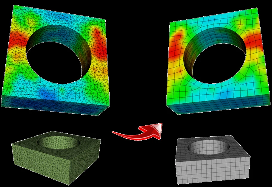
Stress contour mapped from a fine donor mesh onto a coarser receiver structural mesh
Fiber orientation and stress data mapped from a fine process mesh onto a coarser structural mesh, with mapping-quality error indicators.
03

Manufacturing-to-Structural Mesh Mapping

Digimat-MAP transfers fiber orientation, volume fraction, aspect ratio, temperature, weld-line location, and residual stress data from a manufacturing-process mesh onto a separate, typically much coarser or differently discretized, structural mesh. Process simulations and structural models are built for different purposes and rarely share a mesh, so this mapping step is what actually lets process-derived material data reach the structural solve intact rather than being discarded or crudely averaged.

Typical Industries
Automotive and electronics OEMs running separate molding-simulation and structural-analysis teams or toolchains.
Expected Outputs
Mapped orientation, volume-fraction, and residual-stress fields on the structural mesh, with quantified mapping-error indicators.
Design Decisions Enabled
Trusting a structural result that reflects real, as-molded material variation instead of a uniform-property approximation.
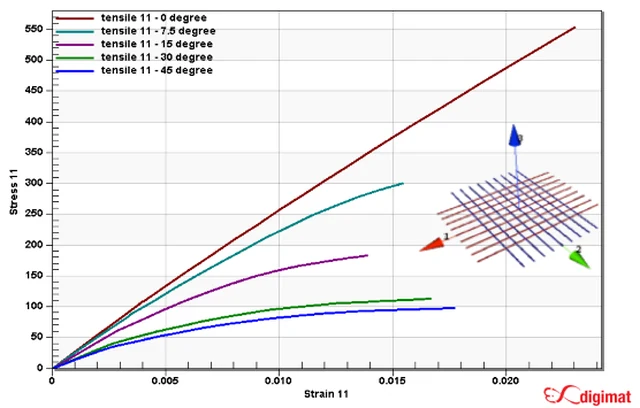
Stress-strain curves at multiple loading angles relative to fiber direction
Calibrated stress-strain response at five loading angles relative to fiber direction — the anisotropic behavior a Digimat material card captures.
04

Anisotropic Material Card Generation & Reverse Engineering

Digimat-MX stores anisotropic experimental measurements and calibrates — "reverse engineers" — the corresponding micromechanical model parameters so the resulting material model matches real coupon test data as closely as possible, across loading angles, strain rates, and temperatures. The platform also ships with a public database of pre-built material models from major resin and compound suppliers, cutting the from-scratch characterization work needed for common grades.

Typical Industries
Material suppliers publishing simulation-ready datasheets, OEMs qualifying a specific compound grade for a program.
Expected Outputs
A calibrated, encryptable material model file usable directly in downstream structural analysis; datasheet-format reports.
Design Decisions Enabled
Selecting between competing material grades or suppliers based on calibrated, apples-to-apples predicted performance.
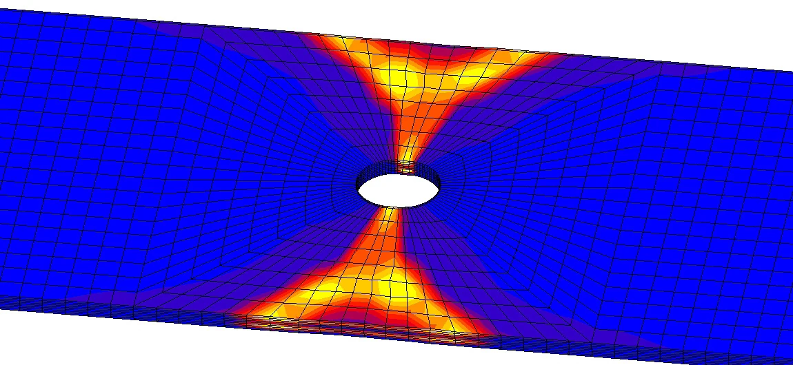
Coupled stress contour result on a plate with a hole, from a Digimat-to-Marc plug-in simulation
A coupled structural result computed with locally-varying, orientation-dependent material properties via the Digimat-to-Marc plug-in.
05

Coupled Structural-Material Simulation

Digimat-CAE is the coupling layer that bridges a manufacturing-derived microstructure to a full structural finite element analysis, through native plug-ins into Marc, Nastran (SOL400), Abaqus, ANSYS, LS-DYNA, and other solvers. Analysts choose between micro, macro, or hybrid coupling strategies to balance accuracy against solve time. This is the step where a molding-process prediction and a calibrated material model actually become a structural result.

Typical Industries
Automotive body and powertrain components, semiconductor and electronics packaging, any reinforced-plastic structural part.
Expected Outputs
Deformation, stress, and strain results computed with locally-varying, orientation-dependent material behavior.
Design Decisions Enabled
Sizing and validating a reinforced-plastic or composite part against its real, as-manufactured stiffness and strength distribution.
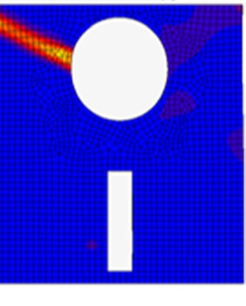
Damage concentration contour on an open-hole tension composite coupon
Damage concentration radiating from a hole edge on an open-hole tension coupon — a progressive-failure result used to set design allowables.
06

Progressive Failure & Fatigue Modeling for Composites

Digimat implements a broad set of failure and damage criteria — maximum stress and strain, Tsai-Hill, Tsai-Wu, Hashin, and others, plus a pseudo-grain-based fatigue model developed specifically for short-fiber reinforced plastics — evaluated at the micro, macro, or per-phase scale. Digimat-VA extends this into virtual allowables generation, running a full test matrix of simulated coupon tests to compute statistical strength values, letting component design proceed in parallel with the physical allowables campaign.

Typical Industries
Aerospace composite structures, automotive crash and durability components, any cyclically or statically loaded reinforced-plastic part.
Expected Outputs
Failure indicator fields, damage progression maps, fatigue life predictions, statistically-derived (mean, A-basis, B-basis) allowable strength values.
Design Decisions Enabled
Setting design allowables and prioritizing reinforcement or layup changes at the locations most likely to fail first.
07

Cure-Dependent Behavior & Process-Induced Residual Stress

Beyond fiber-filled thermoplastics, Digimat models thermoset and curing material systems: cure kinetics, cure-dependent stiffness and CTE, and cure shrinkage, rather than the simplified constant-modulus, constant-CTE, linear-shrinkage assumptions that miss how a material's behavior actually evolves through the cure cycle. This is the material-modeling foundation behind GTECH ASIA's transfer-molding and package-reliability workflow: capturing epoxy molding compound (EMC) behavior accurately enough to predict the residual stress state a package is left with once molding and curing are complete, before that stress state is carried forward into reliability analysis.

Typical Industries
Semiconductor and electronics packaging (transfer and compression molding), automotive and industrial parts using thermoset composites.
Expected Outputs
Cure-state-dependent modulus and CTE, cure shrinkage predictions, process-induced residual stress fields at end of cure.
Design Decisions Enabled
Selecting molding compound formulations and cure profiles that minimize residual stress and warpage before physical trials.
Layered stress contour on a composite sandwich panel under bending
Through-thickness stress on a composite sandwich panel under bending — a virtual replacement for an iterative physical test program.
08

Sandwich & Lightweight Structure Design

Digimat-HC models composite sandwich panels — typically a honeycomb or foam core between fiber-reinforced skins — computing core properties from cell geometry and bulk material properties, and skin properties from ply layup, fiber type, and orientation, using the same micromechanics engine as the rest of the platform. Coupled bending and in-plane shear analyses evaluate the full panel design under realistic loading, with through-thickness stress and failure-indicator results for both the skin and the core.

Typical Industries
Aerospace and industrial lightweight panel structures, automotive body panels, protective and enclosure structures.
Expected Outputs
Through-thickness stress and strain distributions, core and skin failure indicators, predicted failure load and mode.
Design Decisions Enabled
Selecting core cell geometry, skin layup, and panel thickness to meet a stiffness or failure-load target with minimum weight.
Typical Workflow

How these capabilities connect in practice

A Digimat study connects a material characterization step, a manufacturing-process simulation, and a structural solver — in that order.

Characterize the material

Build a micromechanical model (Digimat-MF or Digimat-FE) and calibrate it against available coupon test curves or datasheet information (Digimat-MX), across the loading angles, strain rates, and temperatures relevant to the application.

Simulate the manufacturing process

Run an injection, transfer, or compression molding simulation to predict local fiber orientation, volume fraction, weld lines, and — for thermosets — cure state across the part.

Map microstructure onto the structural mesh

Use Digimat-MAP to transfer the process-derived orientation, volume-fraction, and residual-stress data from the manufacturing mesh onto the structural mesh, checking mapping-quality error indicators along the way.

Generate the coupled material model

Digimat-CAE assigns the mapped, spatially-varying material properties to the structural model, choosing a micro, macro, or hybrid coupling strategy for the accuracy-versus-speed trade-off the study needs.

Run the structural solve

The calibrated, locally-varying material model is solved inside Marc, Nastran SOL400, Abaqus, ANSYS, LS-DYNA, or another supported FEA solver, alongside whatever mechanical, thermal, or reliability loading the study requires.

Correlate against test data and iterate

Results are checked against physical coupon or component test data where available, and the microstructure model, process parameters, or material grade are refined for the next iteration.

Applications by Industry

Where these capabilities are put to work

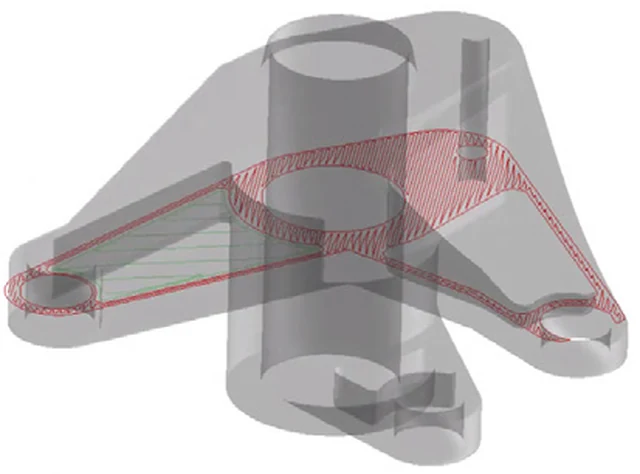
Metal automotive bracket with a candidate zone highlighted for composite redesign
A candidate zone for metal-to-composite redesign, evaluated against the stiffness and strength margins the original metal design relied on.

Automotive

Redesigning metal brackets, mounts, and structural components in reinforced plastic without losing stiffness and strength margins, accounting for the fiber orientation the injection molding process actually produces.

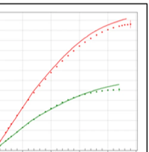
Validated stress-strain curve for an epoxy molding compound material model
A calibrated material model validated against real coupon data — the accuracy basis for predicting package reliability.

Semiconductor & Electronics Packaging

Modeling epoxy molding compound behavior through cure, and carrying the resulting residual stress state through moisture and thermal cycling conditioning to predict die crack, delamination, and package crack risk before physical qualification.

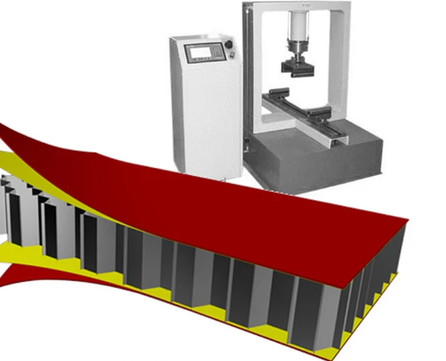
Composite honeycomb sandwich panel with a physical bend-test rig
A honeycomb sandwich panel design, evaluated virtually against the same bending load a physical test rig would apply.

Aerospace & Advanced Composites

Generating and validating composite material models and statistically-derived design allowables for CFRP and other advanced composite structures, reducing the physical coupon-testing burden of a traditional allowables campaign.

Stress or property contour mapped onto a voxelized woven composite structure
A property contour on a woven composite microstructure — the resolution behind predicting real, orientation-dependent part performance.

Consumer & Industrial Products

Predicting the real, orientation-dependent stiffness and strength of injection-molded reinforced-plastic housings and structural components, and evaluating lightweight sandwich-panel designs for enclosures.

Interoperability

Where Digimat fits in a wider simulation stack

Digimat's role in a wider simulation stack is to feed a calibrated, microstructure-aware material model into whichever structural solver the study runs in — it is a materials layer, not a competing structural solver.

The primary structural partner for GTECH ASIA's Digimat workflows; Digimat-CAE's native Marc plug-in passes calibrated material models directly into Marc for nonlinear composite and package-reliability analysis.

Digimat material models couple into Nastran's SOL400 nonlinear solution sequence, supplying calibrated composite behavior in place of simplified constant-property assumptions.

Injection & Compression Molding Solvers

Moldflow, Moldex3D, Sigmasoft, and similar tools supply the local fiber-orientation, weld-line, and cure-state data that Digimat-RP and Digimat-MAP read as process input.

Provides thermal boundary conditions relevant to cure simulation and in-service thermal cycling of Digimat-modeled materials.

FAQ

Frequently asked technical questions

What's the difference between Digimat-MF and Digimat-FE?

Digimat-MF uses mean-field homogenization — fast, analytical schemes such as Mori-Tanaka — to compute a composite's macroscopic response from per-phase properties and microstructure statistics. Digimat-FE instead builds and meshes an actual representative volume element (RVE) and solves it with an embedded finite element or FFT/spectral solver, giving a more geometry-explicit view of the microstructure at higher computational cost.

Does Digimat replace the structural solver we already use?

No. Digimat characterizes and calibrates material behavior and, where relevant, maps process-derived microstructure onto a structural mesh; the actual structural solve — static, dynamic, thermal, or reliability — still runs in Marc, Nastran, or another supported FEA solver, using the material model Digimat produced.

How does Digimat account for the fiber orientation a real molding process produces, rather than assuming a fixed layup?

Digimat-RP reads local fiber orientation, volume fraction, and aspect ratio directly from an injection, injection-compression, or compression molding simulation, and Digimat-MAP transfers that spatially-varying data onto the structural mesh, so the structural solve sees the material properties the part actually has at each location rather than a single averaged value.

Can Digimat model cure-dependent behavior for thermoset materials like epoxy molding compound?

Yes. Digimat models cure kinetics and cure-dependent stiffness, CTE, and shrinkage, rather than treating those properties as constant, which is the basis for predicting process-induced residual stress in transfer-molded and other thermoset-cured parts.

What structural solvers can consume a Digimat material model?

Marc, Nastran (SOL1XX/SOL400/SOL700), Abaqus (Standard and Explicit), ANSYS, LS-DYNA (Implicit and Explicit), PAM-CRASH, SAMCEF, and PERMAS are all supported through native Digimat-CAE interfaces.

How is a Digimat material model validated before it's trusted for design decisions?

Digimat-MX's reverse-engineering tools calibrate model parameters against real coupon stress-strain curves across loading angles, strain rates, and temperatures, and the resulting model can be checked with finite element models of the original test coupons — dumbbells, open-hole or filled-hole specimens — to confirm the calibrated model reproduces the physical test result before it's used on a full part.

GTECH ASIA supplies and supports Digimat licensing for engineering teams across Malaysia and Southeast Asia, with HRD Corp certified training available for teams building in-house material modeling capability.