Cadence · CFD & Conjugate Heat Transfer Solver

Cradle CFD: Electronics Thermal & Airflow Simulation Capabilities

Cradle CFD is a computational fluid dynamics and conjugate heat transfer solver used to predict airflow, temperature, and heat flow through electronic systems before hardware exists. This page works through what the solver actually does, its core capabilities, and how it fits a thermal engineer's design workflow, as a technical reference rather than a product pitch.

Solver ClassCFD & conjugate heat transfer (CHT) solver
DeveloperSoftware Cradle (Cadence Design Systems portfolio)
Core Solution TypesSteady-state & transient CFD, conjugate heat transfer, electro-thermal co-simulation
Model ScaleChip and package level up to full enclosure / system-level assembly
Focus AreaPurpose-built for electronics and power-electronics thermal design
Overview

What Cradle CFD actually is

Cradle CFD is a computational fluid dynamics solver, not a CAD or drafting tool. Given a meshed model of an electronic assembly — chip, package, PCB, heat sink, fan, and enclosure — together with power dissipation values and boundary conditions, it solves for the airflow (or liquid-flow) field and the resulting temperature distribution across every part of that assembly. Where a structural solver like Nastran answers "will this part survive its loads," Cradle CFD answers "will this part run hot enough to fail, throttle, or degrade" — a question central to electronics design as power density rises with AI accelerators, chiplet-based packaging, and denser board layouts.

Cradle CFD is positioned specifically around the electronics-cooling problem rather than as a general-purpose fluid solver. It moves through the full thermal chain a piece of electronic hardware actually experiences: heat is generated at the chip, spreads through the package, conducts through the PCB, is removed by a heat sink or cold plate, dissipated to the surrounding enclosure air, and ultimately rejected by the system as a whole. That chain has historically been analyzed stage by stage with simplified boundary assumptions; Cradle CFD is built to model it as one connected thermal-fluid system instead.

A distinguishing characteristic of the tool is how much of the traditional CFD pre-processing burden — CAD cleanup, geometry simplification, manual tetrahedral meshing, PCB reconstruction — it automates. Complex electronics assemblies with hundreds of parts are notoriously slow to mesh by hand, and engineers have traditionally spent more time preparing a solvable model than solving the thermal problem itself. Cradle CFD's meshing and import automation targets that model-preparation time directly, so effort goes into interpreting results and iterating on cooling design rather than fighting the mesh.

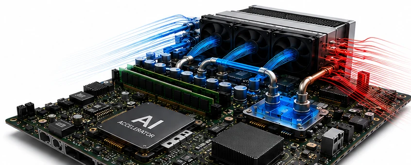
Populated accelerator board with cool-side and hot-side airflow streamlines overlaid
Forced-air cooling airflow direction through a densely populated accelerator board — cool intake air (blue) drawn across components, hot exhaust air (red) expelled downstream.
Capabilities

Nine core capabilities, explained

Each capability below is a distinct function inside Cradle CFD. For each one: what it solves, why engineers reach for it, the industries that depend on it most, the results it produces, and the design decisions those results are actually used to make.

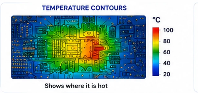
Temperature contour on a populated PCB showing a hot region with a Celsius color-bar legend
A coupled temperature field on a populated PCB — the direct output of solving conduction and convection together rather than assuming a fixed boundary coefficient.
01

Conjugate Heat Transfer (CHT)

Conjugate heat transfer solves solid conduction and fluid convection as one coupled problem instead of treating them separately with an assumed convection coefficient. Heat generated in a chip conducts through solder, substrate, and PCB copper layers, then transfers into moving air or liquid at each solid-fluid interface — CHT solves all of it simultaneously, so temperature at any point reflects the real interaction between the solid heat path and the surrounding flow field, rather than a boundary-condition guess. This is the foundational capability most other electronics-cooling analysis in Cradle CFD builds on.

Typical Industries
Semiconductor packaging, electronics manufacturing, power electronics, telecom hardware.
Expected Outputs
Coupled temperature fields across solids and fluids, junction and case temperatures, heat flux at every solid-fluid interface.
Design Decisions Enabled
Confirming a chip's junction temperature stays within its rated limit under a specific enclosure and airflow configuration.
02

Turbulent Flow & Convection Cooling Modeling

Airflow through a densely packed enclosure — around fans, heat sinks, cables, and component obstructions — is rarely smooth or uniform; it separates, recirculates, and creates dead zones with poor cooling even when average airflow looks adequate. Cradle CFD resolves this turbulent, three-dimensional flow field rather than assuming idealized uniform airflow, and computes both forced convection (fan- or pump-driven) and natural convection (buoyancy-driven, for passively cooled or fanless designs) so an engineer can see where flow actually reaches a hot component and where it doesn't.

Typical Industries
Electronics enclosures, telecom cabinets, data center hardware, industrial control panels.
Expected Outputs
Velocity and streamline fields, recirculation and dead-zone identification, pressure drop across the flow path.
Design Decisions Enabled
Repositioning fans, vents, or baffles to route airflow toward components that are currently starved of cooling.
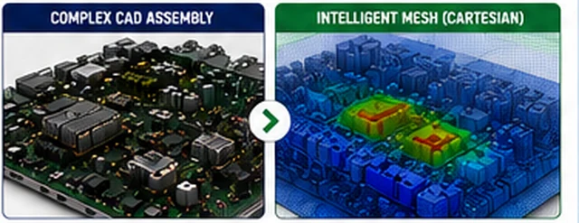
Complex electronics CAD assembly converted into a colored intelligent Cartesian mesh
A complex electronics assembly converted directly into a solver-ready Cartesian mesh — the model-preparation step that traditionally consumes the most time in electronics CFD.
03

Automated Solver-Ready Meshing

Cradle CFD generates solver-ready Cartesian meshes automatically from complex electronics CAD, meshing assemblies of hundreds of parts without the extensive manual geometry cleanup and tetrahedral meshing a traditional CFD workflow requires. Adaptive mesh refinement then concentrates cell density only where it's needed — thin gaps, small features, boundary layers near hot surfaces — while keeping the mesh coarse elsewhere, which improves accuracy at critical interfaces without inflating total cell count or solve time.

Typical Industries
Electronics and semiconductor packaging, any product development team running iterative thermal design studies.
Expected Outputs
A solver-ready volume mesh built directly from CAD, with refinement automatically concentrated at thin gaps and boundary layers.
Design Decisions Enabled
Running more design variants within a given schedule, because model preparation no longer dominates the design cycle.
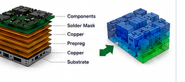
Exploded PCB layer stack-up diagram showing components, solder mask, copper, prepreg and substrate transformed into a meshed board model
Native PCB layer stack-up — components, solder mask, copper, prepreg, and substrate — imported directly into a meshed board model without manual reconstruction.
04

PCB & Component-Level Thermal Modeling

Cradle CFD imports PCB manufacturing data directly (via ODB++), preserving the real copper, solder mask, prepreg, and layer stack-up rather than requiring the board to be manually reconstructed as a simplified block. For chip packages, compact thermal models replace detailed internal package geometry with equivalent thermal-resistance networks that reproduce the same external thermal behavior at a fraction of the mesh size — reducing model size and solve time while also avoiding the need to expose a supplier's proprietary internal package construction.

Typical Industries
PCB and package-level electronics design, semiconductor component suppliers, contract electronics manufacturing.
Expected Outputs
A CFD-ready board model with accurate copper/dielectric layer conductivity, and compact package models with matched external thermal response.
Design Decisions Enabled
Trusting board- and package-level temperature predictions without a time-consuming manual re-build of every layer or package.
05

Liquid Cooling & Hybrid System Modeling

As chip and rack power density outpaces what air cooling alone can remove, Cradle CFD models liquid-cooled cold plates, coolant loops, and hybrid air-plus-liquid configurations alongside conventional air cooling, rather than being limited to one cooling mode. This lets an engineer evaluate the same electronic assembly under an air-cooled baseline and a liquid-cooled alternative within the same modeling environment, which matters directly for AI and high-performance-computing hardware where air cooling is running out of headroom.

Typical Industries
AI/HPC hardware, data center and server design, high-power semiconductor packaging.
Expected Outputs
Coolant flow and pressure-drop distribution, cold-plate surface temperature, comparative temperature results across cooling strategies.
Design Decisions Enabled
Deciding at what power density a design must transition from air cooling to liquid cooling, and sizing the liquid loop accordingly.
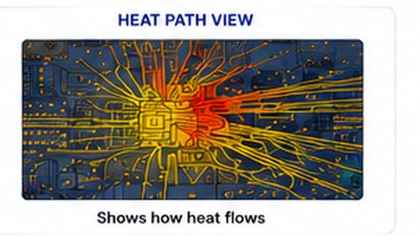
Heat path view showing traced heat-flow lines radiating outward from a hot component on a circuit board
Traced heat-flow paths radiating from a hot component — turning a temperature contour's "where" into a ranked "why."
06

Thermal Bottleneck Diagnostics (Heat Path Analysis)

A temperature contour shows where a hot spot exists but not why — Cradle CFD's heat path analysis traces the flow of heat through the assembly and ranks the specific components and interfaces (thermal interface material, power stage, chip package, heat sink) by their percentage contribution to a given thermal bottleneck. This turns a hot-spot map into a ranked, actionable diagnosis, so design effort goes toward the interface actually limiting performance instead of the component that merely happens to look hottest in a contour plot.

Typical Industries
Power electronics, semiconductor packaging, any high-power-density electronic assembly.
Expected Outputs
Ranked contribution of each component/interface to a thermal bottleneck, alongside standard temperature contour and heat-path visualizations.
Design Decisions Enabled
Targeting a design fix — a better thermal interface material, a redesigned power stage layout — at the actual root cause of a hot spot.
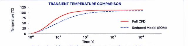
Transient temperature comparison chart, full CFD versus reduced-order model, temperature in degrees Celsius against time
Transient temperature rise from a full-fidelity CFD solve compared against a reduced-order model — the two curves track closely at a fraction of the run time.
07

Transient Thermal Analysis & Reduced-Order Modeling

Transient thermal simulation captures how temperature rises and stabilizes over time under time-varying power loads or duty cycles — startup, load steps, workload bursts — rather than only the steady-state end state. Because fine transient meshes and small time steps can otherwise take hours to run, Cradle CFD can convert a detailed CFD model into a reduced-order model (ROM) that reproduces the same transient temperature response at substantially higher speed, making it practical to sweep many operating scenarios or duty cycles instead of just one.

Typical Industries
AI/HPC hardware under bursty workloads, automotive power electronics, any duty-cycled electronic system.
Expected Outputs
Time-history temperature curves at defined locations, transient hot-spot progression, a validated reduced-order model for repeat use.
Design Decisions Enabled
Sizing thermal mass, heat sinks, or throttling thresholds against realistic time-varying loads instead of a worst-case steady state alone.
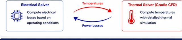
Block diagram of an electrical solver and thermal solver exchanging temperature and power-loss data
Electrical and thermal solvers exchanging temperature and power-loss data — a two-way coupling instead of a one-way assumption.
08

Electro-Thermal Co-Simulation

Electrical losses raise component temperature, and temperature in turn changes electrical performance (resistance, switching losses, leakage) — treating either side as fixed produces an inaccurate result. Cradle CFD's electro-thermal co-simulation exchanges power-loss and temperature data between an electrical solver and the thermal CFD solve, updating both sides iteratively so operating temperature and power loss converge to a physically consistent, mutually dependent result rather than a one-way assumption.

Typical Industries
Power electronics, semiconductor devices with strong temperature-dependent losses, automotive and industrial power modules.
Expected Outputs
Converged operating temperature and power-loss values, accounting for temperature-dependent material and device properties.
Design Decisions Enabled
Predicting real operating temperature (not a fixed-power estimate) for accurate reliability and derating decisions.
09

System-Level Thermal Design Exploration

Rather than validating a chip, a board, or an enclosure in isolation, system-level thermal design exploration evaluates the full chain — chip, package, PCB, cooler, enclosure, and system — together, so a change made at one level (a different heat sink, a repositioned fan) can be assessed for its effect on the whole assembly. Combined with faster meshing and reduced-order models, this supports running a wider set of what-if scenarios and design variants within the same schedule that a component-level check alone would consume.

Typical Industries
AI/HPC hardware, data center systems, advanced packaging programs, any product with a defined system-level thermal budget.
Expected Outputs
System-level temperature and airflow results across the full chip-to-enclosure chain, comparative results across design variants.
Design Decisions Enabled
Allocating a fixed thermal budget across chip, board, and enclosure design choices before committing to hardware.
Typical Workflow

How these capabilities connect in practice

A Cradle CFD study moves from geometry import through mesh generation, solving, and diagnosis, iterating on the cooling design as needed.

Import and prepare geometry

CAD assemblies and PCB manufacturing data (via native ODB++ import) are brought in directly, with complex chip packages optionally replaced by compact thermal models to reduce model size.

Generate a solver-ready mesh

Automated Cartesian meshing builds a mesh from the assembly in minutes, with adaptive refinement concentrating detail at thin gaps, boundary layers, and other critical regions.

Define boundary conditions and heat sources

Component power dissipation, fan curves or coolant flow rates, ambient conditions, and — where relevant — the electrical solver coupling for electro-thermal co-simulation are applied.

Solve

The CFD/CHT solver computes the coupled flow and temperature fields, as steady-state or transient, at full fidelity or via a reduced-order model for faster scenario sweeps.

Post-process and diagnose

Temperature contours, airflow streamlines, and heat-path/bottleneck rankings are reviewed to identify which component or interface is actually limiting thermal performance.

Iterate on the cooling design

Heat sink, fan placement, enclosure venting, or the air-to-liquid cooling strategy is adjusted and re-run — often across many variants, using the faster meshing and reduced-order modeling to keep iteration cycles short.

Applications by Industry

Where these capabilities are put to work

Electronics & Semiconductor

Thermal design of chips, packages, and PCBs under rising power density from AI accelerators, chiplet integration, and 2.5D/3D packaging — the core use case this tool is built around, from single-component thermal resistance checks through full-board and full-system cooling design.

Automotive

Thermal management of power electronics modules, control units, and battery-adjacent electronics, where components must operate reliably across wide ambient temperature ranges and duty cycles without exceeding automotive-grade thermal limits.

Data Centers & Telecom

Cooling design for server, switch, and telecom hardware where rack-level power density increasingly pushes designs from air cooling toward liquid cooling, and where system-level thermal budgets span chip, chassis, and room-level airflow.

Industrial Equipment

Thermal qualification of control cabinets, drives, and power conversion equipment operating continuously in enclosed or harsh environments, where passive natural-convection cooling is often the only option and margin against thermal limits must be verified analytically.

Interoperability

Where Cradle CFD fits in a wider simulation stack

Cradle CFD's fluid-flow and convective results supply the thermal and thermal-structural boundary conditions that feed into Nastran's thermal analysis and thermal-structural coupling studies. Coupled with Marc, those same thermal results support the most demanding nonlinear thermal-mechanical stress problems, such as thermal expansion at component and package interfaces. Digimat supplies temperature-dependent material properties for composite and plastic enclosure or package components used in a coupled thermal-structural study. Geometry from CrownCAD's cloud-native 3D CAD environment can be brought directly into a Cradle CFD thermal model as part of the same design workflow.

Receives fluid-flow and convective thermal boundary conditions for thermal analysis and thermal-structural coupling studies.

Takes Cradle CFD thermal results forward into the most demanding nonlinear thermal-mechanical stress problems.

Supplies temperature-dependent material properties for composite and plastic components in a coupled thermal-structural study.

Cloud-native 3D CAD geometry can be brought directly into a Cradle CFD thermal model as part of the same design workflow.

Electrical Solvers

Exchange power-loss and temperature data with Cradle CFD's thermal solver for electro-thermal co-simulation, rather than being fixed inputs.

FAQ

Frequently asked technical questions

What's the difference between conjugate heat transfer and a simple convection-coefficient boundary condition?

A convection-coefficient boundary condition assumes a fixed heat transfer rate at a surface, estimated in advance. Conjugate heat transfer solves the solid conduction and the fluid flow together, so the actual convection at each surface emerges from the real airflow pattern around it — which matters wherever airflow is uneven, recirculating, or partially blocked, as it typically is inside a populated enclosure.

When is transient thermal analysis needed instead of a steady-state solve?

Steady-state analysis is sufficient when power dissipation is constant and the question is the final equilibrium temperature. Transient analysis is needed whenever load varies over time — startup, workload bursts, duty cycles — because peak temperature during a transient event can exceed the eventual steady-state value, and thermal mass and time-to-throttle only show up in a time-resolved solve.

What is electro-thermal co-simulation and why does it matter for accuracy?

It's a two-way exchange between an electrical solver and Cradle CFD's thermal solver: electrical losses set the heat source for the thermal solve, and the resulting temperature feeds back to update temperature-dependent electrical losses. Solving each side once with a fixed assumption for the other systematically over- or under-predicts operating temperature; iterating the coupling converges on a physically consistent result.

How does Cradle CFD handle large, complex electronics assemblies without excessive manual meshing?

Through automated Cartesian meshing that builds a solver-ready mesh directly from CAD in minutes rather than days, adaptive refinement that concentrates mesh density only where needed, native PCB import that preserves board layer detail without manual reconstruction, and compact thermal models that replace detailed package internals with equivalent thermal-resistance representations.

Can Cradle CFD model liquid cooling as well as air cooling?

Yes. Alongside conventional forced- and natural-convection air cooling, it models liquid-cooled cold plates and coolant loops, and hybrid air-plus-liquid configurations, within the same modeling environment — relevant as power density in AI and HPC hardware increasingly exceeds what air cooling alone can remove.

What is a reduced-order model (ROM) and how does it speed up thermal design exploration?

A ROM is a lightweight model derived from a detailed, high-fidelity CFD solve that reproduces the same transient temperature response at substantially higher speed. Once generated, it lets an engineer sweep many operating scenarios, duty cycles, or design what-ifs — the kind of exploration that would be impractical if every variant required a full high-fidelity transient solve.

GTECH ASIA supplies and supports Cradle CFD licensing for engineering teams across Malaysia and Southeast Asia, with HRD Corp certified training available for teams building in-house electronics thermal simulation capability.