
Cadence · Vibro-Acoustic & Aeroacoustic Solver

Actran: Vibro-Acoustic & Aeroacoustic Simulation Capabilities

Actran predicts how a vibrating structure or a moving airflow generates, transmits, and radiates sound — before a physical prototype exists. This page works through what the solver actually does, capability by capability, as a technical reference rather than a product pitch.

Solver ClassVibro-acoustics & aeroacoustics solver (FEM / BEM / infinite elements)
DeveloperFree Field Technologies lineage, Hexagon / MSC Software (Cadence portfolio)
Core Solution TypesAcoustic radiation, structural-acoustic coupling, electroacoustic transduction, aeroacoustics, transmission loss
Model ScaleA single loudspeaker driver to a full appliance enclosure or vehicle cabin
HistoryDedicated vibro-acoustic FEM/BEM solver used in automotive NVH and electroacoustics since the late 1990s
Overview

What Actran actually is

Actran is a dedicated vibro-acoustics and aeroacoustics solver, not a general-purpose structural or CFD code. It takes a vibrating surface, an enclosed or exterior acoustic domain (air, another fluid, or a porous/absorptive material), an electroacoustic transducer model, or a turbulent flow field as input, and computes the sound pressure, sound power, and radiated noise those sources produce. Where a structural solver like Nastran answers "how does this part move," and a CFD solver like Cradle CFD answers "how does the air move around this part," Actran answers "how loud is it, at what frequencies, and where does the sound come from" — the question that ultimately determines whether a product feels well-engineered to the person using it.

Under the hood, Actran couples finite element modeling of the near-field acoustic domain (the air inside an enclosure, or immediately around a vibrating panel) with boundary element or infinite element formulations that represent sound radiating outward into free space without needing to mesh all the way to infinity. Porous and absorptive materials — foams, felts, mesh grilles — are represented with equivalent-fluid or Biot-theory material models rather than as simple rigid boundaries, which matters because these materials are exactly what designers use to damp resonances and absorb radiated noise in enclosures. This is also why Actran rarely runs standalone: it needs a source. That source is either a structural vibration result (mode shapes and forced-response velocities from Nastran or Marc), a turbulent flow field (from Cradle CFD), or an electrical excitation converted to mechanical force through an embedded loudspeaker/transducer model.

GTECH ASIA supports two coupled workflows built around this same underlying solver. The first — Nastran + Actran, an Electro-Vibro-Acoustic (EVA) workflow — carries a signal from electrical input through voice-coil force, cone motion, and enclosure vibration to radiated sound, used for Bluetooth speakers, earbuds, and similar audio devices. The second — Cradle CFD + Nastran + Actran — carries a signal from airflow through structural vibration to radiated and flow-generated noise, used for air purifiers, vacuum cleaners, and similar home appliances. Both converge on the same acoustic solve; what differs is where the noise originates.

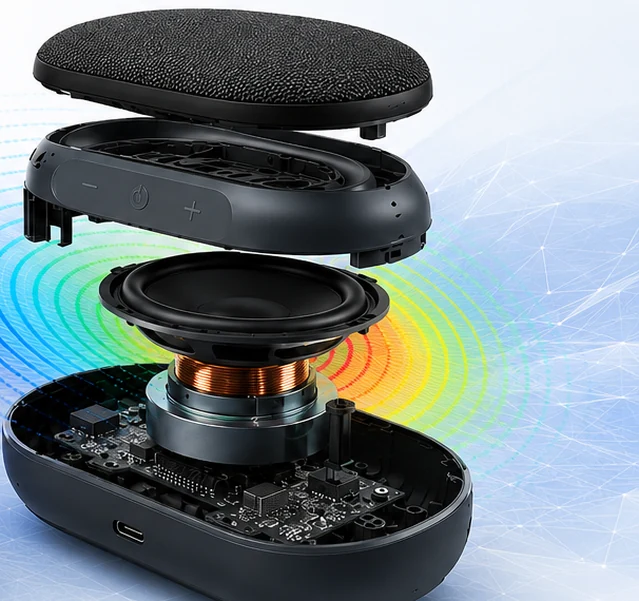
Exploded-view render of a Bluetooth speaker showing driver, voice coil, PCB and enclosure with radiating sound arcs
An exploded Bluetooth speaker assembly — driver, voice coil, PCB, and enclosure — the kind of coupled electro-vibro-acoustic system Actran is used to evaluate before a prototype is built.
Capabilities

Eight core capabilities, explained

Each capability below is a distinct function inside Actran. For each one: what it solves, why engineers reach for it, the industries that depend on it most, the results it produces, and the design decisions those results are actually used to make.

01

Acoustic Radiation & Sound Power Prediction

Acoustic radiation analysis takes the surface velocity of a vibrating structure — a speaker cone, an appliance housing panel, a duct wall — and computes the sound pressure field it generates in the surrounding air, along with the total radiated sound power and directivity pattern. This is the fundamental link between "the structure is vibrating" and "a person can hear it," and it's the calculation every other acoustic result in Actran ultimately depends on. Because radiation efficiency varies strongly with frequency, panel size, and shape, a structure with identical vibration amplitude can radiate very different amounts of audible noise depending on its geometry — which is why radiated sound power, not vibration amplitude alone, is the metric acoustic engineers actually design against.

Typical Industries
Consumer electronics and audio, home appliances, automotive NVH, industrial equipment.
Expected Outputs
Sound pressure level (SPL) fields and contours, total radiated sound power, directivity balloon plots.
Design Decisions Enabled
Identifying which panels or components dominate radiated noise, so damping or stiffening effort is targeted where it actually reduces perceived loudness.
02

Structural-Acoustic Coupling

Structural-acoustic coupling solves the vibrating structure and the surrounding or enclosed acoustic domain as a single coupled system, rather than treating the acoustic field as a one-way consequence of structural motion. Air inside an enclosure — a speaker cabinet, an appliance housing, a vehicle cabin — has its own resonant cavity modes, and those modes can reinforce or interact with the panel vibration modes of the structure containing them, changing the radiated or perceived sound in ways a structure-only or acoustics-only analysis would miss. It's also the mechanism used to trace unwanted structure-borne noise — including buzz, squeak, and rattle (BSR) from loose or resonant panels — back to the specific vibration mode responsible.

Typical Industries
Consumer audio devices, automotive interiors, home appliances, industrial enclosures.
Expected Outputs
Coupled mode shapes, panel contribution analysis ranking each surface's share of total radiated noise, interior cavity SPL.
Design Decisions Enabled
Repositioning stiffeners, ribs, or mounting points to de-tune a panel or cavity resonance before it becomes an audible rattle or tonal peak.
03

Electroacoustic Transducer Simulation

Electroacoustic transducer simulation models a loudspeaker or microphone as a coupled electrical-mechanical-acoustic system: an electrical signal drives current through the voice coil, the resulting Lorentz force moves the speaker cone, and that motion becomes the structural vibration source for the rest of the acoustic model. Modeling the transducer this way — rather than approximating it as a generic vibrating surface — lets the simulation capture how driver-specific parameters (coil resistance and inductance, magnetic field strength, suspension stiffness) shape the eventual frequency response and sound output, which is what makes it possible to evaluate a driver-and-enclosure combination before either is physically built.

Typical Industries
Consumer audio devices, smart speakers, telecommunications and conferencing equipment.
Expected Outputs
Voltage-to-SPL frequency response, electrical impedance curves, voice-coil displacement and force.
Design Decisions Enabled
Selecting driver size, magnet strength, and enclosure volume for a target frequency response and output level before committing to tooling.
04

Transmission Loss & Sound Insulation

Transmission loss analysis computes how much acoustic energy is blocked, rather than transmitted, as sound passes through a partition — a housing wall, an acoustic enclosure, a barrier panel — as a function of frequency. It's the calculation behind any noise-containment design decision: adding mass, changing panel thickness, or introducing a damping or absorptive layer all change transmission loss in frequency-dependent ways, and the analysis shows which frequency bands actually benefit before a material or construction change is committed to.

Typical Industries
Home appliances, industrial equipment enclosures, automotive cabin insulation, building and HVAC acoustics.
Expected Outputs
Transmission loss curves versus frequency, insertion loss for added barrier or damping treatments.
Design Decisions Enabled
Choosing enclosure wall construction, gasket sealing, or absorptive lining to meet a target noise-containment level without over-specifying mass.
05

Aeroacoustics & Flow-Induced Noise

Aeroacoustics computes the noise generated directly by moving air — tonal noise at a fan's blade-passing frequency and its harmonics, broadband noise from turbulence at filter edges, grilles, and sharp corners, and noise from flow separation and recirculation — using flow field data (velocity, pressure fluctuation, turbulence quantities) as the acoustic source rather than a vibrating structure. This is the dominant noise mechanism in any product built around a fan, blower, or forced airflow path, and it exists independently of structural vibration, which is why an aero-acoustic study is run alongside, not instead of, the structural-acoustic analysis of the same product.

Typical Industries
Home appliances (air purifiers, vacuum cleaners, fans), HVAC equipment, automotive climate and ventilation systems, industrial blowers.
Expected Outputs
Blade-passing-frequency tonal peaks, broadband turbulence noise spectra, sound power by noise source, SPL at a defined listening position.
Design Decisions Enabled
Redesigning fan blade geometry, grille spacing, or duct routing to cut tonal or broadband noise without sacrificing airflow performance.
06

Cabin & Enclosure Acoustics

Cabin and enclosure acoustics analyzes the interior air volume as its own acoustic system, computing the standing-wave cavity modes and interior sound pressure distribution that develop inside a bounded space. An enclosure's internal geometry, volume, and any internal partitions or absorptive material change which frequencies resonate and how evenly sound pressure is distributed inside it, and those internal resonances directly shape what a listener hears, whether that's bass response inside a speaker cabinet or interior noise level inside a vehicle cabin.

Typical Industries
Consumer audio enclosures, automotive interiors, appliance housings, conferencing and telecommunications equipment.
Expected Outputs
Interior cavity mode shapes and frequencies, interior SPL distribution maps, acoustic mode-based porting or venting guidance.
Design Decisions Enabled
Sizing enclosure volume, port/vent placement, and internal bracing to avoid exciting an audible cavity resonance in the product's operating range.
07

Duct & Muffler Acoustics

Duct and muffler acoustics computes how sound propagates along an air path — an appliance's inlet or outlet duct, a speaker port, an HVAC duct run — including the attenuating or amplifying effect of duct geometry, cross-section changes, resonant chambers, and absorptive lining along the way. Because ducts and ports are also the direct exit path for fan and flow noise, this capability is frequently paired with aeroacoustic analysis to evaluate whether a given duct design attenuates the noise generated upstream or simply carries it straight through to the listener.

Typical Industries
Home appliances, HVAC systems, automotive intake and exhaust paths, industrial ventilation equipment.
Expected Outputs
Duct transmission loss and insertion loss curves, resonant chamber attenuation performance, exit-plane SPL and spectrum.
Design Decisions Enabled
Sizing resonant chambers, lining material, or duct bends to attenuate specific tonal frequencies without adding excessive pressure drop.
08

Psychoacoustic Metrics for Product Sound Quality

Psychoacoustic post-processing converts raw sound pressure and frequency-response results into perceptually weighted metrics — loudness, sharpness, tonality, and frequency-response balance across the audible range — that correlate more closely with how a listener actually judges sound quality than raw SPL or sound power alone do. Two products can have identical overall SPL and still sound noticeably different in quality; psychoacoustic metrics are how that difference gets quantified and tracked as a design target, rather than left to subjective listening alone.

Typical Industries
Consumer audio devices, automotive interior sound quality, home appliances marketed on "quiet" performance.
Expected Outputs
Frequency-response balance curves, loudness and tonality metrics, comparative SPL curves between design iterations.
Design Decisions Enabled
Tuning enclosure, driver, or damping parameters toward a target sound signature, not just a minimum SPL threshold.
Typical Workflow

How these capabilities connect in practice

An Actran study always starts from an upstream vibration or flow source and ends with correlated, perceptually meaningful results.

Import the structural or flow source data

Modal and forced-response vibration results are imported from Nastran (or Marc for nonlinear cases), or a turbulent flow field is imported from Cradle CFD, depending on whether the noise being studied is structure-borne or flow-generated.

Build the acoustic mesh and domain

The interior cavity, exterior free-field radiation domain, or duct geometry is meshed, with infinite elements or absorbing boundary formulations used to represent radiation into unbounded space without meshing to infinity.

Define the sources and excitation

Vibrating surface velocities, an electroacoustic transducer's electrical input, or a flow-derived aeroacoustic source are applied, along with any porous or absorptive material properties in the domain.

Solve across the frequency range

The coupled structural-acoustic, electroacoustic, or aeroacoustic problem is solved at each frequency of interest, typically spanning the full audible range relevant to the product.

Post-process sound pressure, power, and directivity

SPL contours, sound power, directivity patterns, and panel or component noise-contribution rankings are reviewed to identify dominant noise sources and paths.

Correlate against physical test data and iterate

Simulated frequency response and SPL are compared against microphone or listening-test measurements where available, and the design — driver, enclosure, fan, duct, or damping treatment — is revised for the next iteration.

Applications by Industry

Where these capabilities are put to work

Consumer Electronics & Audio

Smart speakers, Bluetooth speakers, earbuds, headphones, and conferencing devices, where the design question is simultaneously electroacoustic (driver and frequency response), structural (enclosure resonance and buzz/rattle), and acoustic (radiated sound and directivity).

Home Appliances

Air purifiers, vacuum cleaners, fans, air conditioners, and kitchen appliances built around a fan or blower, where fan tonal noise, broadband turbulence noise, and housing panel vibration all contribute to the noise a user actually experiences.

Automotive NVH

Interior cabin acoustics, powertrain and road noise transmission into the cabin, and exterior pass-by noise, where structural vibration results from Nastran feed directly into the acoustic radiation and cabin-acoustics analysis.

Industrial Equipment

Rotating and fan-driven machinery, HVAC equipment, and enclosed industrial equipment where noise exposure limits or product noise specifications require quantifying and reducing both structure-borne and flow-generated noise.

Interoperability

Where Actran fits in a wider simulation stack

Actran is built to consume, not duplicate, results from GTECH ASIA's other simulation tools, since it needs a vibration or flow source to compute an acoustic result. Nastran supplies modal and forced-response structural vibration results that become Actran's structural excitation source in the EVA workflow. Marc supplies nonlinear structural results — large-deflection housings or contact-heavy assemblies — for cases a linear Nastran solve doesn't capture accurately. Cradle CFD supplies the turbulent flow field data that Actran's aeroacoustic capability converts into fan tonal and broadband noise sources. Digimat supplies calibrated material models for damping-critical components such as foam, felt, or composite acoustic-treatment panels.

Supplies modal and forced-response structural vibration results that become Actran's structural excitation source in the EVA workflow.

Supplies nonlinear structural results — large-deflection housings or contact-heavy assemblies — for cases a linear solve doesn't capture accurately.

Supplies the turbulent flow field data that Actran's aeroacoustic capability converts into fan tonal and broadband noise sources.

Supplies calibrated material models for damping-critical components such as foam, felt, or composite acoustic-treatment panels.

FAQ

Frequently asked technical questions

What's the difference between structural-acoustic coupling and aeroacoustics?

Structural-acoustic coupling computes sound generated by a vibrating structure — a speaker cone or housing panel physically moving air. Aeroacoustics computes sound generated by the airflow itself — fan tones and turbulence — independent of any structural vibration. Most real products, especially fan-driven appliances, need both analyzed together because both contribute to the total noise a user hears.

Can Actran predict loudspeaker sound quality without a physical prototype?

Yes, within the limits of the transducer and material models used. The Electro-Vibro-Acoustic workflow carries an electrical input through voice-coil force, cone motion, enclosure vibration, and radiated sound in one coupled simulation, producing a predicted frequency response and SPL that can be evaluated and iterated before a driver or enclosure is built — though results are still typically correlated against physical measurement once a prototype exists.

How does Actran model sound radiating into open space without meshing to infinity?

Through boundary element or infinite element formulations at the edge of the meshed domain, which represent the correct radiation behavior into an unbounded exterior region without requiring the mesh itself to extend indefinitely outward.

Does an aeroacoustic study require CFD data, or can Actran compute flow noise on its own?

Aeroacoustic analysis needs a flow field — velocity, pressure fluctuation, and turbulence data — as its source, which is why the appliance workflow pairs Actran with Cradle CFD. Actran itself doesn't solve the fluid flow; it converts flow data already computed elsewhere into radiated and propagated noise.

What's the difference between sound pressure level (SPL) and sound power?

SPL is a location-specific measurement of acoustic pressure at a defined point, such as a listener's ear or a fixed measurement distance, and changes with distance and surroundings. Sound power is a property of the source itself — the total acoustic energy radiated — independent of where or how far away it's measured, which makes it the more consistent metric for comparing noise output between design alternatives.

Why use psychoacoustic metrics instead of just minimizing overall SPL?

Two designs with identical overall SPL can sound noticeably different in perceived quality depending on tonality, frequency balance, and loudness distribution across frequency bands. Psychoacoustic metrics quantify those perceptual qualities directly, so a design target can be "reduce tonal harshness at the fan blade-passing frequency" rather than just "reduce overall dB," which better reflects how a product is actually judged by the people using it.

GTECH ASIA supplies and supports Actran licensing for engineering teams across Malaysia and Southeast Asia, with HRD Corp certified training available for teams building in-house vibro-acoustic simulation capability.