Cadence · Welding Process Simulation Platform

Simufact Welding: Distortion, Residual Stress & Process Simulation Capabilities

Simufact Welding is a manufacturing-process simulation platform used to predict how a welded assembly will distort, where residual stress will concentrate, and how weld sequence, fixturing, and process parameters change both outcomes — before a single physical weld is made.

Solver ClassManufacturing process simulation platform (welding module)
DeveloperSimufact Engineering, Hexagon Manufacturing Intelligence (Cadence portfolio)
Core Solution TypesCoupled thermal-metallurgical-mechanical welding simulation, distortion & residual-stress prediction, weld sequence/fixture optimization
Model ScaleA single weld seam to a multi-weld body-in-white or chassis-level assembly
HistoryPurpose-built process simulation platform, brought into the Cadence portfolio through Hexagon's acquisition of Simufact Engineering
Overview

What Simufact Welding actually is

Simufact Welding is not a structural solver in the Nastran or Marc sense — it is a process simulation tool. Where a structural solver takes a finished, as-designed part and asks how it behaves in service, Simufact Welding takes a nominal, undistorted assembly and a defined welding process — seam locations, weld sequence, heat input, fixture and clamping layout — and predicts what actually comes out of the welding operation: a distorted, residually stressed part that may or may not match the nominal CAD geometry it started from. GTECH ASIA positions it specifically for this purpose: predicting and optimizing welding processes virtually before production, to reduce distortion, cut scrap and rework, and avoid relying on physical trial-and-error.

Under the hood, welding is a coupled multi-physics problem. A moving heat source melts and re-solidifies material along a seam, driving a transient temperature field that in turn drives thermal expansion, phase transformation in the heat-affected zone, and — once the assembly cools — locked-in residual stress and permanent shape change. Simufact Welding solves this as a coupled thermal, metallurgical, and mechanical problem rather than a purely mechanical one, because treating a weld as a simple mechanical load would miss the metallurgical changes and thermal history that actually govern where distortion and residual stress end up. The platform covers a range of thermal joining processes beyond conventional arc welding — including laser welding, resistance spot welding, laser brazing, furnace brazing, and directed energy deposition — reflecting that the underlying physics is common across these processes even though the equipment and parameters differ.

In practice, Simufact Welding sits downstream of CAD and upstream of both the shop floor and other simulation tools. It consumes assembly geometry and weld-seam definitions, and its outputs — a predicted distorted shape and residual stress field — are useful both directly, correcting fixture design or weld sequence before tooling is cut, and as an input to further analysis, such as feeding a welded assembly's residual-stress-affected geometry into a downstream structural or fatigue study.

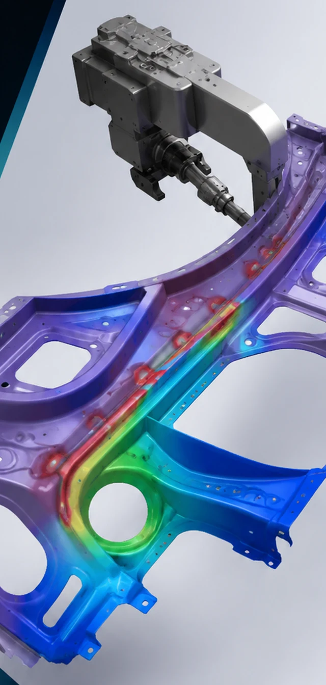
Distortion and residual-stress contour on a welded automotive subframe assembly with a robotic welding arm
A predicted distortion/stress contour on a welded automotive subframe — the direct output of a coupled thermal-metallurgical-mechanical weld simulation.
Capabilities

Eight core capabilities, explained

Each capability below is a distinct function inside Simufact Welding. For each one: what it solves, why engineers reach for it, the industries that depend on it most, the results it produces, and the design decisions those results are actually used to make.

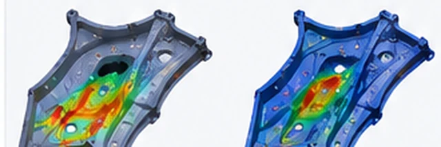
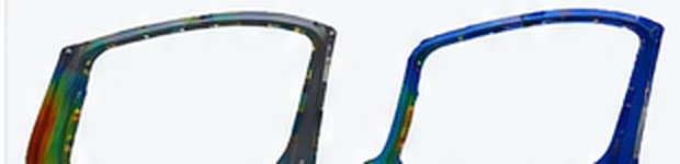
Before and after distortion contour comparison on an automotive door frame assembly
A before/after distortion comparison on a door-frame assembly — the kind of result distortion prediction is used to evaluate before tooling is cut.
01

Welding Distortion Prediction

Distortion prediction simulates how an assembly's geometry changes as welds are made and the part cools — warping, bowing, twisting, or shrinkage away from nominal CAD dimensions. Welding is a localized, uneven heating and cooling event, and the resulting non-uniform thermal expansion and contraction is the direct cause of most weld-induced shape error. Engineers use this capability to see, before any metal is cut, whether a proposed design and weld plan will hold dimensional tolerance, and to identify which seams or regions are the largest contributors to overall part distortion.

Typical Industries
Automotive body and chassis fabrication, industrial machinery and equipment structures.
Expected Outputs
Predicted distorted shape overlaid on nominal geometry, distortion magnitude at defined measurement points, deviation contour maps.
Design Decisions Enabled
Adjusting seam layout, weld sequence, or adding pre-bow/compensation to the as-designed geometry so the as-welded part lands within tolerance.
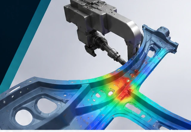
Residual stress contour on a welded chassis assembly with concentrated stress along a weld seam
Locked-in stress concentrated along a weld seam and its intersections — invisible to a dimensional check, but a recognized contributor to fatigue crack initiation.
02

Residual Stress Analysis

Residual stress analysis computes the stress field that remains locked into a welded structure after all thermal transients have died out and the part has fully cooled — stress that exists with no external load applied. This matters because residual stress adds to whatever service loads a structure later experiences, and it is a recognized contributor to fatigue crack initiation and, in some material and geometry combinations, to stress-corrosion cracking. Because it is invisible to a simple visual or dimensional check, simulation is one of the only practical ways to locate it before it becomes a field failure.

Typical Industries
Automotive structural and safety-critical welds, industrial equipment subject to cyclic loading.
Expected Outputs
Residual stress contour maps (through-thickness and surface), peak stress location and magnitude at weld toes and HAZ boundaries.
Design Decisions Enabled
Selecting weld sequence, heat input, or post-weld treatment to keep residual stress away from locations that will also carry high service load.
03

Thermal-Metallurgical-Mechanical Coupling

This is the core coupled solve that the other capabilities draw on: a transient thermal analysis computes the moving temperature field from the heat source, a metallurgical model tracks phase transformation and hardness change as material heats and cools through its transformation temperatures, and a mechanical analysis computes the resulting thermal-expansion-driven stress and deformation — with each physics feeding the others rather than running independently. Welding cannot be represented accurately as a mechanical-only problem, because the driving cause of distortion and residual stress is the thermal and metallurgical history of the material, not a mechanical load applied after the fact.

Typical Industries
Any welded metal structure where distortion, residual stress, or HAZ properties are a design concern — automotive and industrial fabrication in particular.
Expected Outputs
Transient temperature fields, phase fraction and hardness distributions, and the coupled stress/displacement results derived from them.
Design Decisions Enabled
Selecting a heat input and travel speed combination that achieves adequate fusion without excessive thermal distortion or unwanted hardness change.
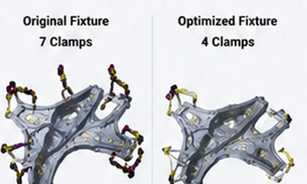
Comparison of an original seven-clamp fixture layout against an optimized four-clamp fixture layout
Comparing an original clamp layout against a reduced-clamp alternative — the kind of fixture question this capability is used to answer before tooling is committed.
04

Weld Sequence & Fixture/Clamping Optimization

The order welds are made in, and how (and where) an assembly is clamped while they're made, both change the final distortion and residual stress outcome — often more than the weld parameters themselves — because each new weld interacts with the stiffness and stress state left by the ones before it. This capability lets engineers compare alternative weld sequences and fixture/clamping layouts virtually, evaluating each against predicted distortion before committing to tooling. It is one of the more directly actionable capabilities, because sequence and fixture changes are typically far cheaper to implement than a design or material change.

Typical Industries
Automotive body-in-white and chassis assembly, general fabricated metal structures with multiple welds.
Expected Outputs
Comparative distortion results across candidate sequences or fixture layouts, ranked by resulting distortion or residual stress.
Design Decisions Enabled
Choosing a weld order and clamp count/placement that minimizes distortion without over-specifying fixture complexity.
05

Heat-Affected-Zone Microstructure Prediction

Material adjacent to a weld — the heat-affected zone (HAZ) — is heated enough to undergo microstructural transformation without being melted, which can change its hardness, ductility, and strength relative to the parent material. This capability models the phase transformation and hardness change through that zone as a function of the local thermal cycle (peak temperature and cooling rate), rather than assuming HAZ properties equal the base material. It's the metallurgical half of what makes the thermal-metallurgical-mechanical coupling accurate rather than purely geometric.

Typical Industries
Automotive and industrial fabrication using steels and alloys sensitive to heat-treatment-like transformation during welding.
Expected Outputs
Phase fraction maps, predicted hardness distribution through the HAZ, cooling-rate-based transformation indicators.
Design Decisions Enabled
Adjusting heat input or process selection to avoid excessive HAZ hardening or softening in locations that matter for downstream mechanical performance.
06

Weld Quality & Process Parameter Evaluation

Beyond distortion and residual stress at the assembly level, this capability evaluates the weld joint's own quality indicators — penetration depth, melt-pool/melt-flow behavior, and seam consistency — as a function of the process parameters used (heat input, travel speed, and process-specific settings). It gives engineers a way to check whether a proposed parameter set is likely to produce a sound joint before it's run on the shop floor, rather than relying solely on downstream inspection.

Typical Industries
Automotive and industrial welded joints where joint integrity, not just part shape, is a qualification requirement.
Expected Outputs
Predicted penetration depth and melt-pool geometry, process-parameter sensitivity results.
Design Decisions Enabled
Tuning heat input, travel speed, or process choice to achieve adequate penetration without excess heat input, and the distortion that comes with it.
07

Multi-Process Joining Coverage

The underlying coupled thermal-metallurgical-mechanical approach is applied across several thermal joining processes documented in GTECH ASIA's Simufact Welding materials: arc welding (including MIG, MAG, and TIG variants), laser welding, resistance/projection spot welding, laser brazing, furnace brazing, and directed energy deposition. Because each process differs mainly in how heat is delivered — an arc, a laser beam, resistive current at a spot, or a furnace — rather than in the physics that follows, a common simulation approach can represent all of them, letting a fabrication plan spanning multiple joining methods be evaluated in one environment.

Typical Industries
Automotive (arc, spot, laser), industrial machinery and equipment fabrication (arc, brazing).
Expected Outputs
Process-specific heat input and distortion/residual-stress predictions, comparable across joining methods on the same assembly.
Design Decisions Enabled
Choosing which joining process is appropriate for a given joint, or substituting one process for another (e.g., laser for arc) with a predicted distortion impact.
Before and after distortion contour on a full structural weldment assembly
Cumulative distortion across a full multi-weld structural assembly, before and after sequence and reinforcement optimization.
08

Assembly-Level, Multi-Weld Simulation

Real fabricated structures — a chassis subframe, a body-in-white shell, an industrial equipment frame — carry many welds interacting on the same part, where each subsequent weld both responds to and adds to the distortion and stress state left by the ones before it. This capability runs a full assembly-level sequence of welds as a single simulation, rather than evaluating individual seams in isolation, so the cumulative, order-dependent effect on final part shape and stress state is captured the way it actually occurs in production.

Typical Industries
Automotive body and chassis structures, industrial equipment frames and structural assemblies with multiple weld joints.
Expected Outputs
Cumulative distortion and residual-stress state across a full multi-weld assembly, seam-by-seam contribution breakdown.
Design Decisions Enabled
Identifying which specific welds in a large assembly drive the majority of total distortion, so mitigation effort is targeted rather than spread evenly.
Typical Workflow

How these capabilities connect in practice

A Simufact Welding study moves from geometry and weld-plan definition through a coupled solve to sequence and fixture optimization.

Import assembly geometry

CAD geometry for the parts to be welded is imported, along with (where available) scanned or as-measured geometry for dimensional correlation against nominal CAD.

Define weld seams and sequence

Weld seam locations, joint type, and the order in which welds will be made are defined on the assembly.

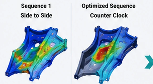
Comparison of two candidate weld sequences and their resulting distortion contours
Two candidate weld sequences on the same assembly — sequence choice changes the resulting distortion pattern as much as, or more than, the weld parameters themselves.

Set fixture and process parameters

Fixture/clamping layout, joining process (arc, laser, resistance spot, brazing, directed energy deposition), and process parameters — heat input, travel speed — are configured for each seam.

Mesh and solve the coupled simulation

The assembly is meshed and the coupled thermal-metallurgical-mechanical simulation is run through the full weld sequence.

Post-process distortion, stress, and HAZ results

Predicted distortion, residual stress, and heat-affected-zone properties are reviewed against tolerance and quality targets.

Optimize and re-run

Weld sequence, fixture layout, or process parameters are adjusted based on the results, and the simulation is re-run to confirm the change achieves the intended reduction before it's committed to production tooling.

Applications by Industry

Where these capabilities are put to work

Automotive Body & Chassis

Automotive is the industry GTECH ASIA's own Simufact Welding materials name explicitly, and it is where multi-weld, tight-tolerance assemblies — body-in-white structures, chassis subframes, door frames — make distortion and residual-stress prediction most directly valuable. Weld sequence and fixture optimization are used to keep dimensional variation within assembly tolerance across structures carrying dozens of individual welds.

Industrial Machinery & Equipment

Also explicitly named in GTECH ASIA's source material. Fabricated equipment frames and structural weldments are evaluated for distortion and joint quality before fixtures and welding procedures are finalized, reducing reliance on physical trial-and-error for one-off or low-volume fabricated structures.

Shipbuilding & Heavy Fabrication

Large welded steel structures in shipbuilding and heavy fabrication involve long seams and heavy sections where cumulative distortion across an assembly is a known, industry-wide production concern, addressed generically by welding process simulation to plan sequence and fixturing for large weldments.

Rail

Rail vehicle structures — car bodies and bogie frames — are welded assemblies with dimensional and fatigue requirements broadly similar to automotive chassis work, where the same distortion- and residual-stress-prediction approach generically applies.

Interoperability

Where Simufact Welding fits in a wider simulation stack

Simufact Welding's outputs are most useful when they feed into GTECH ASIA's broader Cadence simulation stack rather than standing alone. A welded assembly's predicted distorted shape and residual-stress field can be carried into a Nastran structural model as the actual, as-built starting condition for downstream durability, stiffness, or NVH analysis, rather than analyzing the nominal, undistorted CAD geometry. For welded assemblies requiring detailed nonlinear structural evaluation — large local deformation, contact, or nonlinear material response after welding — Marc can take the welded, residually stressed geometry as its starting model. As GTECH ASIA's cloud-native CAD offering, CrownCAD is a natural source of the assembly geometry and weld-seam definitions Simufact Welding consumes as input.

Receives the welded assembly's predicted distorted shape and residual-stress field as the as-built starting condition for downstream durability, stiffness, or NVH analysis.

Takes the welded, residually stressed geometry as its starting model for detailed nonlinear structural evaluation.

A natural source of the assembly geometry and weld-seam definitions Simufact Welding consumes as input.

FAQ

Frequently asked technical questions

What's the difference between distortion prediction and residual stress analysis?

Distortion is the visible, geometric outcome — how far the part's final shape deviates from nominal CAD. Residual stress is the internal, invisible stress state left behind after cooling. The two come from the same coupled thermal-mechanical history and are usually reported together, but a part can carry significant residual stress without much visible distortion, or vice versa, depending on how the assembly's stiffness constrains it during welding.

Why does weld sequence matter if the total heat input into the part is the same either way?

Each weld responds to the stiffness and stress state left by the welds made before it. Welding a symmetric pattern from the center outward, for example, generally distorts a part differently than welding straight across in one direction, even with identical individual welds — because the structure's ability to resist distortion changes as each weld is added and constrains the next.

How does the simulation predict heat-affected-zone properties, not just overall part shape?

By tracking the local thermal cycle — peak temperature and cooling rate — at each point in the material adjacent to the weld, and applying a metallurgical transformation model to predict resulting phase fractions and hardness, rather than treating the HAZ as unchanged base material.

Can welding simulation results be used directly in a structural fatigue study?

The residual stress field and as-welded (distorted) geometry it produces can be carried into a downstream structural solver as the starting condition for a fatigue or durability analysis, since residual stress adds to whatever service load a structure subsequently experiences and materially affects fatigue life prediction.

Does the simulation only cover arc welding, or other joining processes too?

GTECH ASIA's Simufact Welding materials document coverage across several thermal joining processes — arc welding (MIG/MAG/TIG), laser welding, resistance/projection spot welding, laser brazing, furnace brazing, and directed energy deposition — reflecting that the same coupled thermal-metallurgical-mechanical approach applies wherever a localized or moving heat source creates a joint.

How does fixture and clamping strategy factor into the result, and can it be changed without a full re-weld study?

Fixture and clamping layout constrain how a part is free to distort while each weld is made and cools, so it's modeled as an explicit input alongside weld sequence and parameters. Because it's a simulation input rather than a physical setup, alternative clamp counts or positions can be compared in the same environment without cutting new tooling for each option.

GTECH ASIA supplies and supports Simufact Welding licensing for engineering teams across Malaysia and Southeast Asia, with HRD Corp certified training available for teams building in-house welding process simulation capability.